Bit timing(can总线BT时间确定-用于确定波特率)


Bit timing
(can总线BT时间确定-用于确定波特率) timing(can
CAN has advanced features for coping with the time delays found in long bus lengths(in comparison to the bit rate)and coping with differences in clock chrystal frequencies for nodes on the bus.
The choice of bit timing is very important since it decides the bit rate,the sample point and the ability to resynchronise.
Bit segments(as in Bosch standard)
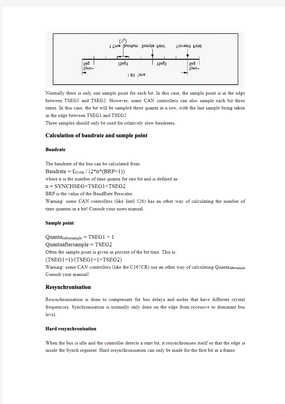
Each bit is divided into four segments-the synchronisation segment,the propagation segment and the phase segments one and two.Each segment consists of one or more time quanta.
A time quantum is a fixed amount of time which is derived from the CAN controller clock with a prescale factor.
Synchronisation segment(Synch_Seg)
The synchronisation segment is used to synchronise the various nodes on the bus.When a bit is sent on the bus,the leading edge is expected to be within this segment.
This segment is always one time quantum long.
Propagation segment(Prop_Seg)
The Propagation Segment is needed to compensate for the delay in the bus lines.
The segment size is programmable between1and8time quanta.
Phase Segment1(Phase_Seg1),Phase Segment2(Phase_Seg2)
These segments can be used lengthened or shortened by resynchronisation.
Bit segments(as in implementations like Intel527and C167CR)
In most implementations of CAN controllers the segments seem to be implemented in a different way than described in the standard.The synch segment looks as in the standard and consists of one time quantum.The big difference is that the propagation segment and the phase segment1in the standard have been combined into one segment,TSEG1.Phase segment2is left untouched, but is renamed to TSEG2.
Normally there is only one sample point for each bit.In this case,the sample point is in the edge between TSEG1and TSEG2.However,some CAN controllers can also sample each bit three times.In this case,the bit will be sampled three quanta in a row,with the last sample being taken in the edge between TSEG1and TSEG2.
Three samples should only be used for relatively slow baudrates.
Calculation of baudrate and sample point
Baudrate
The baudrate of the bus can be calculated from:
Baudrate=f crystal/(2*n*(BRP+1))
where n is the number of time quanta for one bit and is defined as:
n=SYNCHSEG+TSEG1+TSEG2
BRP is the value of the BaudRate Prescaler.
Warning:some CAN controllers(like Intel526)has an other way of calculating the number of time quantas in a bit!Consult your users manual.
Sample point
Quanta beforesample=TSEG1+1
Quantaaftersample=TSEG2
Often the sample point is given in percent of the bit time.This is:
(TSEG1+1)/(TSEG1+1+TSEG2)
Warning:some CAN controllers(like the C167CR)use an other way of calculating Quanta aftersample. Consult your manual!
Resynchronisation
Resynchronisation is done to compensate for bus delays and nodes that have different crystal frequencies.Synchronisation is normally only done on the edge from recessive to dominant bus level.
Hard resynchronisation
When the bus is idle and the controller detects a start bit,it resynchronises itself so that the edge is inside the Synch segment.Hard resynchronisation can only be made for the first bit in a frame.
Resynchronisation within a frame
CAN controllers have the ability to synchronise on bit edges also within a frame.The (re)Synchronisation Jump Width(SJW)decides the maximum number of time quanta that the controller can resynchronise every bit.
?Resynchronisation of a receiver to a slower transmitter is handled as follows:
If a recessive-to-dominant edge appears inside TSEG1and the edge is less than or equal to SJW quanta inside,TSEG1is restarted.If the edge was more than SJW quanta inside,TSEG1is lengthened with SJW quanta.
?Resynchronisation of a receiver to a faster transmitter:
If a recessive-to-dominant edge appears inside TSEG2,TSEG2is shortened by the number of quantas necessary to make the edge be outside TSEG2.However,TSEG2can be shortened no more than SJW quanta.
CAN bus physical layer
The physical layer is not part of the Bosch CAN standard.However,in the ISO standards transceiver characteristics is included.
CAN transmits signals on the CAN bus which consists of two wires,a CAN-High and CAN-Low. These2wires are operating in differential mode,that is they are carrying inverted voltages(to decrease noise interference)The voltage levels,as well as other characteristics of the physical layer,depend on which standard is being used.
ISO11898
The voltage levels for a CAN network which follows the ISO11898(CAN High Speed)standard are described in the picture and table below.
Signal recessive state dominant state unit
min nominal max min nominal max
CAN-High 2.0 2.5 3.0 2.75 3.5 4.5Volt
CAN-Low 2.0 2.5 3.00.5 1.5 2.25Volt
Note that for the recessive state,nominal voltage for the two wires is the same.This decreases the power drawn from the nodes through the termination resistors.These resistors are120ohm and are located on each end of the wires.Some people have played with using central termination resistors (that is,putting them in one place on the bus).This is not recommended,since that configuration will not prevent reflection problems.
ISO11519
The voltage levels for a CAN network which follows the ISO11519(CAN Low Speed)standard are described in the table below.
Signal recessive state dominant state unit
min nominal max min nominal max
CAN-High 1.6 1.75 1.9 3.85 4.0 5.0Volt
CAN-Low 3.1 3.25 3.40 1.0 1.15Volt
ISO115519does not require termination resistors.They are not necessary because the limited bit rates(maximum125kB/s)makes the bus insensitive to reflections.
The voltage level on the CAN bus is recessive when the bus is idle.
Bus lengths
The maximum bus length for a CAN network depends on the bit rate used.It is required that the wave front of the bit signal has time to travel to the most remote node and back again before the bit is sampled.This means that if the bus length is near the maximum for the bit rate used,one should choose the sampling point with utmost care-one the other hand,one should always do that!
Below is a table of different bus lengths and the corresponding maximum bit rates.
Bus length(metres)Maximum bit rate(bit/s)
401Mbit/s
100500kbit/s
200250kpit/s
500125kbit/s
6km10kbit/s
Cable
According to the ISO11898standard,the impedance of the cable shall be120+-12ohms.It should be twisted par,shielded or unshielded.Work is in progress on the single-wire standard SAE J2411.
白玉新
2013.08.08整理
