华硕N61VN Series拆机

Disassembly Procedure
Please follow the information provided in this section to perform the complete disassembly procedure of the notebook. Be sure to use proper tools described before.
SUS N61VN Series Notebook consists of various modules. This chapter describes the procedure for the complete notebook disassembly. In addition, in between procedures, the detailed disassembly procedure of individual modules will be provided for your service needs.
The disassembly procedure consists of the following steps:
? Battery Module ? CPU Module ? Memory Module
? Wireless LAN Module ? HDD Module ? ODD Module ? Keyboard Module ? Top Case Module ? LCD Module
? Motherboard Module ? Bottom Case Module
C h a p t e r
2
A
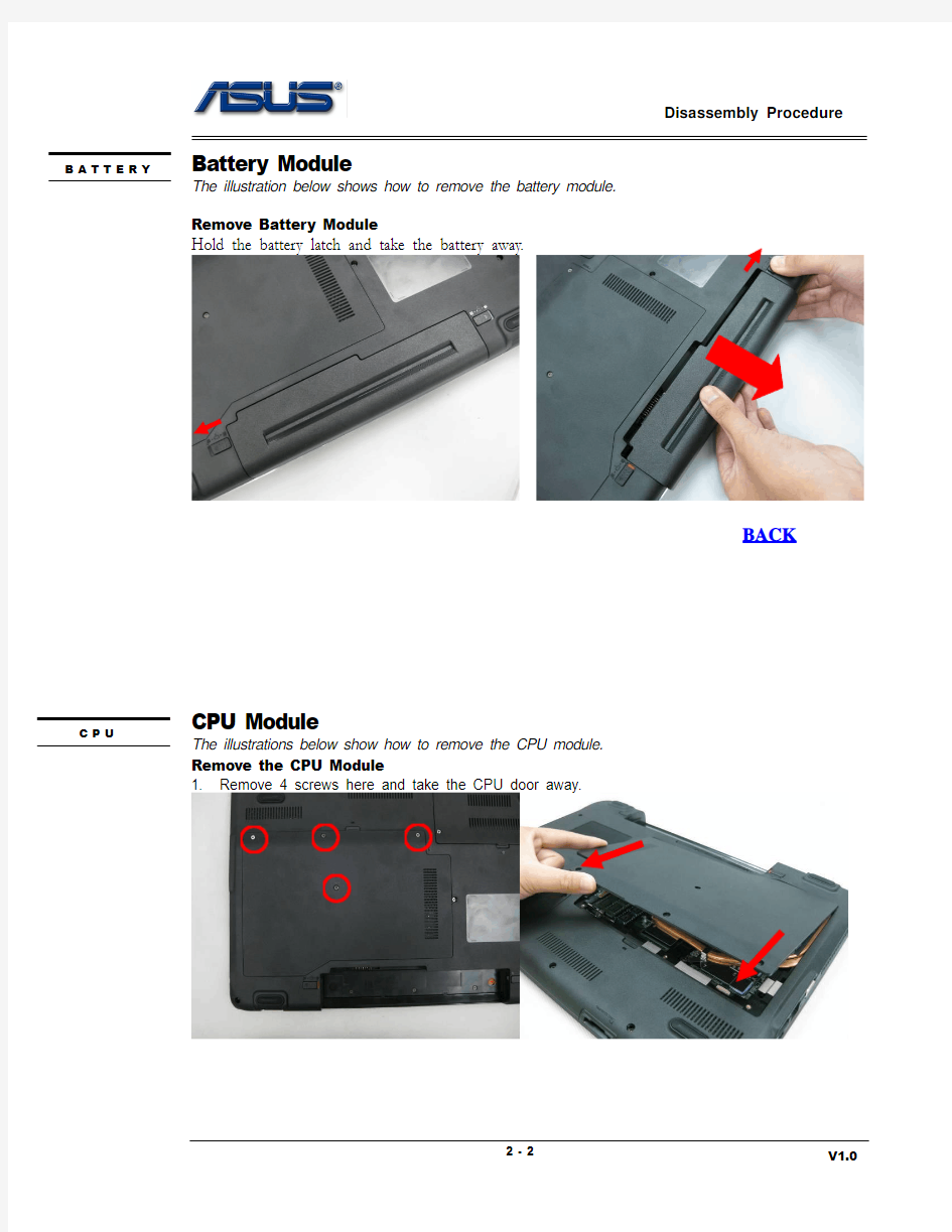
Battery Module
The illustration below shows how to remove the battery module.
Remove Battery Module
Hold the battery latch and take the battery away.
BACK
CPU Module
The illustrations below show how to remove the CPU module. Remove the CPU Module
1. Remove 4 screws here and take the CPU door away.
B A T T E R Y
C P U
2. Disconnect the fan cable and remove 2 screws here, then take the fan away.
3. Remove 8 screws here and take the CPU thermal module away.
4. Turn the non-removable screw here 180 degrees counter-clockwise to loosen the CPU.
5. Squeeze the vacuum handling pump on the CPU and use it to lift the CPU away.
BACK
Memory Module
The illustration shows how to remove the Memory Module.
Remove Memory Module
Pull two latches here to pop the Memory module up at 45 angles, and then pull out the module at that angle.
BACK
M E M O R Y
Wireless LAN Module
The illustration below shows how to remove the Wireless LAN Module from the notebook.
Remove Wireless LAN Module
1. Disconnect the Wireless Land antennas.
2. Remove 2 screws on Wireless LAN card and pull out the card from its slot.
BACK
W L A N
HDD Module
The illustrations below show how to remove the HDD Module from the notebook. Remove HDD Module
1. Remove 2 screws here and take the HDD door away.
2. Remove 3screws here. Lift up the HDD module and take it away.
H D D
2. Remove 4 screws to separate HDD from HDD housing
BACK
ODD Module
O D D
The illustrations below show how to remove the ODD Module.
Remove ODD Module
1.Remove 1 screw here.
2.Pull out the ODD module slowly with a screwdriver push on back.
BACK
Keyboard Module
The illustrations below show how to remove the Keyboard and disassemble the Keyboard Cover.
Remove the Keyboard
1. Open 5 latches (Esc, F5, F9, Prt Sc, End) on keyboard module by a pair of tweezers.
2. Turn over the keyboard plate and tear of the tape here, disconnect the LED cable and the keyboard FPC to remove the keyboard plate.
K E Y B O A R
Remove Keyboard Cable
1. Use a flexible connector tool to unlock the cable connector on both ends (no. 1).
2. Carefully pull out the keyboard cable (no. 2) with a pair of tweezers.
3. Lock the connector (no. 3) again to avoid possible breakage.
BACK
3.
Lock
3.
Lock
Top Case Module
The illustrations below show how to remove and disassemble the Top Case Module.
Remove the Top Case Module
1. Tear off the tape here. Disconnect the instant FFC and touchpad FFC. Remove 4 screws here.
T O P C A S E
Touchpad FFC
Instant FFC
2.Remove 19 screws (6 M2.5*8L+7 M2.5*5L+6 M2*2.5L)on the bottom case.
3.Separate the Top case from the bottom case.
4.Disconnect the latch here and remove the instant FFC. Remove 3 screws here.
Tear off 2 pieces of tape here. Take the instant key board away.
5. Tear off 3 pieces of tape and remove 4 screws here, then take the speakers away.
6.Tear 1 piece of tape off touch pad module and disconnect the touch pad FPC.
7.Remove 5 screws and tear off the Mylar here, then take the touchpad bracket away.
BACK
LCD Module
The illustrations below show how to remove and disassemble the LCD Module of the notebook.
Removing the LCD Module
1.Disconnect the LVDS cable. Release the LVDS cable and WLAN antennas out of hole.
2.Tear off 2 pieces of tape here, and remove 6 screws here.
L C D
3.Remove the LCD module from the bottom case.
BACK
Motherboard Module
The illustrations below show how to disassemble and remove the Motherboard Module.
Remove the Motherboard Module
1. Tear off 2 pieces of tape on the motherboard and disconnect 4 cables here. The DC IN CABLE, POWER BOARD CABLE, BLUETOOTH CABLE, AUDIO BD CABLE.
M O T H E R B O A R D
DC IN CABLE
POWER BOARD
CABLE
AUDIO BOARD
CABLE
BLUETOOTH
CABLE
2.Remove 2 screws here and take the motherboard away.
- 智能电力技术的标准和规范解读
- IEEE标准在智能电网中的应用
- 新一代智能电网调度自动化标准体系研究(1)
- 智能电网行业标准
- 新型电力系统评价标准
- 智能电网的技术和标准体系建设
- 智能电网管理系统的技术要求
- 智能电网的发展和标准化
- 智能电网的数据模型标准
- 肺癌患者报告结局测评工具的研究近况与思考
- 2023非小细胞肺癌新辅助治疗疗效病理评估专家共识
- 肺癌评估标准recist -回复
- DNA甲基化与肺癌疗效及预后判断
- 肺癌质量控制指标
- 临床分析肺癌患者的放疗疗效评估与调整
- 肺癌的放射治疗副作用与效果评估
- 临床分析肺癌患者治疗反应的临床分析与评估
- 实体肿瘤疗效评价标准(recist)
- 肺癌射频消融术后评估及并发症
- 肿瘤疗效评价的新标准