MP1517DR中文资料

EV0043 (MP1517)
3A, 25V, 1.1MHz
Step-Up Converter for WLED Applications
EVALUATION BOARD
The Future of Analog IC Technology
DESCRIPTION
The EV1517 is the evaluation board used to demonstrate the white LED driver capabilities of the MP1517. The low 0.7V feedback voltage offers higher efficiency in white LED driver applications including cell phone camera flash. Soft-start, cycle-by-cycle current limiting and input under voltage lockout prevent overstressing or damage to sensitive external circuitry at startup and output short-circuit conditions. Current-mode regulation and external compensation components allow the MP1517 control loop to be optimized over a wide variety of input voltages, output voltages and load current conditions.
ELECTRICAL SPECIFICATIONS
Parameter Symbol Value Units Input Voltage (1)
V IN
2.6 to 5.5V
LED Current (Torch) I OUT1 20 mA LED Current (Flash)
I OUT2 150
mA Note:
1) 5.5V input voltage limit is specific to the application circuit on this
evaluation board. The input voltage limit of the MP1517 is 25V.
FEATURES
? 4A Peak Current Limit
?
Low 700mV Feedback Threshold ? Internal 150m ? Power Switch ? Input Range of 2.6V to 25V ? 95% Efficiency
? Zero Current Shutdown Mode ? Under Voltage Lockout Protection ? Open Load Protection ? Soft-Start Operation ? Thermal Shutdown
? Tiny QFN16 (4mm x 4mm) Package
APPLICATIONS
? Boost and SEPIC Regulators ? Handheld Computers
? Cell Phone Camera Flash, PDAs ? Digital Still and Video Cameras
“MPS” and “The Future of Analog IC Technology” are Registered Trademarks of Monolithic Power Systems, Inc.
EV0043 EVALUATION BOARD
Dimensions (2.5”X x 2.0”Y x 0.4”Z) Board Number
MPS IC Number
EV0043 MP1517DR
V GATE 2V/div.
V OUT 10V/div.
20ms/div.
EV0043_TPC01
Waveform in Flash Mode
EV0043 (MP1517) – 3A, 25V, 1.1MHz STEP-UP CONVERTER FOR WLED APPLICATIONS
EVALUATION BOARD
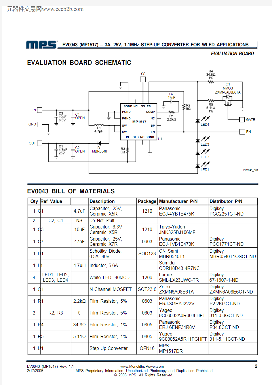
EVALUATION BOARD SCHEMATIC
GATE
EN
EV0043 BILL OF MATERIALS
Qty Ref Value Description Package Manufacturer P/N Distributor P/N 1 C1 4.7uF
Capacitor, 25V, Ceramic X5R
1210 Panasonic
ECJ-4YB1E475K Digikey
PCC2251CT-ND 2 C2, C4 NS Do Not Stuff
1 C3 10uF
Capacitor, 6.3V
Ceramic X5R 1210 Taiyo-Yuden
JMK325BJ106MF
1 C7 47nF
Capacitor, 25V,
Ceramic X7R 0603 Panasonic
ECJ-1VB1E473K
Digikey
PCC1771CT-ND
1 D1
Schottky Diode,
0.5A, 40V
SOD123
ON Semi MBR0540T1 Digikey MBR0540T1OSCT-ND 1 L1 4.7uH Inductor, 5.6A
Sumida
CDRH8D43-4R7NC
4 LED1, LED2, LED3, LED4 White LED, 40MCD 1206
Lumex SML-LX23UWC-TR Digikey 67-1607-1-ND
1 Q1 N-Channel MOSFET SOT23-6
Zetex ZXMN6A08E6TA Digikey
ZXMN6A08E6CT-ND 1 R1 2.2k ? Film Resistor, 5% 0603
Panasonic ERJ-3GEYJ222V Digikey
P2.2KGCT-ND 2 R2, R3 0 Film Resistor, 5% 0603
Yageo 9C06032A0R00JLHFT Digikey
311-0.0GCT-ND 1 R4 34.8? Film Resistor, 1% 0805
Panasonic ERJ-6ENF34R8V Digikey
P34.8CCT-ND 1 R5 5.11? Film Resistor, 1% 0805
Yageo 9C08052A5R11FGHFT Digikey
311-5.11CCT-ND 1 U1 Step-Up Converter QFN16 MPS
MP1517DR
EV0043 (MP1517) – 3A, 25V, 1.1MHz STEP-UP CONVERTER FOR WLED APPLICATIONS
EVALUATION BOARD
NOTICE: The information in this document is subject to change without notice. Please contact MPS for current specifications. Users should warrant and guarantee that third party Intellectual Property rights are not infringed upon when integrating MPS products into any application. MPS will not assume any legal responsibility for any said applications.
PRINTED CIRCUIT BOARD LAYOUT
Figure 1—Top Silk Layer
Figure 2—Top Layer
Figure 3—Bottom Layer
QUICK START GUIDE
1. Connect LEDs to LED1 to LED4 terminals.
2. Connect positive and negative terminals of the 2.5V to 5.5V power supply to the IN and GND
pins, respectively. 3. Drive GATE of Q1 with a pulsed signal to switch between two (2) LED currents.
4. The device is automatically enabled because EN is connected to IN through a 0? resistor (R2).
It will be disabled only if V IN is removed.