Series-Cascaded Rings Dual-band Filter

Series-Cascaded Rings Dual-band Filter Zuhani Ismail Khan1, Mohd Khairul Mohd Salleh2, Noor Zareena Zakaria3
Faculty of Electrical Engineering
Universiti Teknologi MARA (UiTM), 40450 Shah Alam, Malaysia
1rasyiqah03@https://www.wendangku.net/doc/23446679.html,
2khairulsalleh@https://www.wendangku.net/doc/23446679.html,
3zareenazakaria@https://www.wendangku.net/doc/23446679.html,
Abstract — This paper presents a new topology of dual-band
bandpass filter which is based on two series-cascaded ring
resonators and fed via quarter-wavelength coupled-lines.
Based on such topology, a microstrip dual-band filter is
designed and realized on FR4 substrate. The passbands of
the dual-band filter are centered at 0.89 GHz and 1.20 GHz
with relative bandwidths of 18 % and 11 %. Simulated and
measured results are presented throughout this paper to
validate the idea.
Index Terms — Microwave filters, dualband, bandpass
filters, ring resonator.
I.I NTRODUCTION
The increasing demand for various applications and services in actual communication system has led the wireless local area network and mobile communication development to move towards the use of multi-band multi-mode concept whose diverse specification standards may include operating frequencies, modulation bandwidth, power level and etc.
In such environment, dual-band bandpass filter is one of the key components in the frequency transceiver circuits that must be designed according to the stringent specifications such as selectivity, size and cost. Many structures of bandpass filter were developed for a dual-band response such as dual-mode resonator and step impedances resonators, and filters based on parallel coupling [1]-[5]. These designs produce dual-band effects and require additional parameters that need to be considered throughout the simulation process. Therefore the topologies are relatively complicated and circuit simplification is difficult to attain, resulting large physical size of the filter.
An interesting topology presented in [6] involves parallel coupled-line resonator configuration that gives rise mainly to the magnetic coupling between the two coupled lines. The transmission zeros in the filter response can be placed at a chosen frequency such that the initial passband can be divided into two and hence producing a dual-band response.This approach allows the direct design of dual-band resonators and hence reduces the size of the filter.
The work presented in this paper proposes an original dual-band filter topology derived from a quarter-wavelength side-coupled ring resonators which also involves the use of parallel-coupled lines [7].
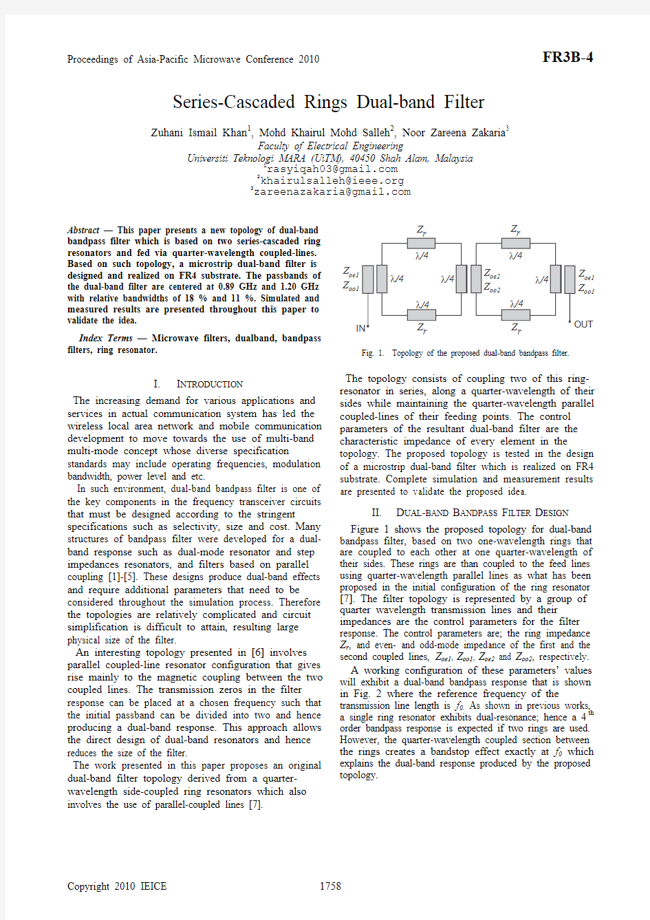
Fig. 1. Topology of the proposed dual-band bandpass filter.
The topology consists of coupling two of this ring-resonator in series, along a quarter-wavelength of their sides while maintaining the quarter-wavelength parallel coupled-lines of their feeding points. The control parameters of the resultant dual-band filter are the characteristic impedance of every element in the topology. The proposed topology is tested in the design of a microstrip dual-band filter which is realized on FR4 substrate. Complete simulation and measurement results are presented to validate the proposed idea.
II.D UAL-BAND B ANDPASS F ILTER D ESIGN Figure 1 shows the proposed topology for dual-band
bandpass filter, based on two one-wavelength rings that are coupled to each other at one quarter-wavelength of their sides. These rings are than coupled to the feed lines using quarter-wavelength parallel lines as what has been proposed in the initial configuration of the ring resonator [7]. The filter topology is represented by a group of quarter wavelength transmission lines and their impedances are the control parameters for the filter response. The control parameters are; the ring impedance Z r, and even- and odd-mode impedance of the first and the second coupled lines, Z oe1, Z oo1, Z oe2 and Z oo2, respectively.
A working configuration of these parameters’ values will exhibit a dual-band bandpass response that is shown in Fig. 2 where the reference frequency of the transmission line length is f0. As shown in previous works, a single ring resonator exhibits dual-resonance; hence a 4th order bandpass response is expected if two rings are used. However, the quarter-wavelength coupled section between the rings creates a bandstop effect exactly at f0 which explains the dual-band response produced by the proposed
topology.
Z
oe1
Z
oo1
Z
Z
oe1
Z
oo1
r
r
Z
Proceedings of Asia-Pacific Microwave Conference 2010FR3B-4
Fig. 2. Frequency response of the proposed dual-band bandpass filter.
Fig. 3. Example of ideal frequency response of the proposed dual-band
bandpass filter for a given set of elements’ impedances.
As shown in Fig. 2, f 1 and f 2 are the center frequencies of the first and the second passbands. The reference frequency f 0 are found exactly at the center between f 1 and f 2. Each bandpass response is of a second order, seen by their two poles in the response. As a result, a very compact second-order dualband bandpass filter can be realized only by using two ring resonators. A total of three transmission zeros are found in the frequency response of the filter and this will ensure a good level of selectivity. As the dual-band filter response is symmetrical about f 0, any dual-band filter of any center frequency can be realized, theoretically, using this concept of topology. It is sufficient to calculate the center frequency f 0 based on the center frequencies f 1 and f 2, of the required passbands using the following equation:
/2
(1)
Therefore all the length of the transmission lines in the filter will be based on the working frequency f 0.
Fig. 4. Circuit layout of the microstrip dual-band filter
Fig. 5. Microstrip dual-band filter
Other characteristics of the filter response such as amount of frequency separation between the passbands, the bandwidth and the in-band ripple level of the passbands, can be varied by varying the impedance of each of the filter elements (Z oe1, Z oo1, Z oe2, Z oo2 and Z r ).
An example of working configuration for the impedances of the filter elements is given in Fig. 3 where Z oe1 = 100 ?, Z oo1 = 28 ?, Z oe2 = 83 ?, Z oo2 = 58 ? and Z r = 40 ?. The reference frequency is chosen to be 1 GHz and in this case, the passbands are centered at 0.835 GHz and 1.165 GHz.
III. D UAL -BAND B ANDPASS F ILTERS R EALIZATION The proposed topology is tested through the design of microstrip dual-band bandpass filter on FR4 substrate whose characteristics are; dielectric constant, εr = 4.55, substrates thickness, h = 1.6 mm and loss tangent, tan δ = 0.0175. The dual-band characteristics are set to follow the ones presented in Fig. 3. The circuit layout of microstrip filter is presented in Fig. 4 whilst Fig. 5 shows its photo.
d B (S ) 11d B (S )
12Frequency
d B (S ) 11d B (S )
12
Fig. 6. Simulated and measured results of the dual-band filter.
Fig. 6. Simulated and measured results of the dual-band filter,
showing wider range of frequency.
Figure 6 shows the measured results of the filter which
agree with the ones from the simulation. The passbands are centered at 0.89 GHz and 1.22 GHz with relative bandwidths of 18 % and 11 %, respectively. The insertion loss of 2.5 dB and 5.2 dB are mainly due to the high loss tangent of the substrate and radiation loss of the microstrip. The dispersion of the material toward the frequency has resulted in the asymmetrical effect between the first and second passbands. Because of the same reason, the center transmission zero that separates the passbands is not exactly located at 1 GHz.
Nevertheless, very good out-of-band rejection level of more than 40 dB is obtained for the areas before the first passband and after the second passband, up to around 3 GHz, as shown in Fig. 6. Furthermore, the passbands are well separated by the center transmission zero whose isolation is found to be as high as 30 dB.
IV. C ONCLUSION
An original topology for dual-band bandpass filter was presented based on the combination of two series- cascaded ring resonators. The characteristics of the filter can be controlled easily by varying the impedance of the filter elements. The filter is designed and realized using the microstrip technology on FR4 substrate to demonstrate the idea. The measured results agree well with the simulations and show two passbands which are well separated with very good out-of-band rejection level.
A CKNOWLEDGMENT
Support from Universiti Teknologi MARA and Ministry of Science, Technology and Innovation (MOSTI) of Malaysia for this project is gratefully acknowledged.
R EFERENCES
[1] M. Zhou, X. Tang, and F. Xiao, “Compact Dual Band Bandpass
Filter Using Novel E-type Resonators with Controllable
Bandwidths,” IEEE Microwave and Wireless Components Letters , vol. 18, no. 12, 2008.
[2] F. Hassam, and S. Boumaiza, “ WCDMA/WIMAX Dual-Band
Bandpass Filter Design Using Frequency Transformation and Circuit Conversion,” 1-4244-1176-8/07 IEEE , 2007.
[3] K. Kim, H. S. Pyo, J. M. An, and Y. Lim, “Dual-band Filter using
Half Wavelength Resonators and Dual-mode Resonators,” 978-1-4244-3388-9/09 IEEE , 2009.
[4] C. Quendo, E. Rius, and C. Person, “An Original Topology of
Dual-Band Filter with Transmission Zeros,” IEEE MTE-S Digest , WEID-7. 2003.
[5] S.S. Myoung, Y. Lee, and J. G. Yook , “,Bandwidth Enhanced
Miniaturization Method of Parallel Coupled-Line Filter,” Asia Pacific Microwave Conference, 1-4244-0749-4/07/IEEE 2007 [6] C.W. Tang, W.T. Liu, M. G. Chen and Y.C. Lin, “Design of Dual-Band Bandpass Filters With Short-end Coupled Line,” European Microwave Conferemce, pp. 1385-1388, 2009
[7] M. K. Mohd Salleh, G. Prigent, O. Pigaglio, and R. A. C. R.
Crampagne, "Quarter-Wavelength Side-Coupled Ring Resonator for Bandpass Filters," Microwave Theory and Techniques, IEEE Transactions on , vol. 56, pp. 156-162, 2008
1.0
0.6
1.5
0.5
-40-30
-20
-10
0.7
0.8
0.9
1.1
1.2
1.3
1.4
d B (S ), 11d B (S )
12Frequency (GHz)
0.5
1.0
1.5
2.0
2.5
3.0
3.5
4.0
0.0
-70-60-50-40-30-20-10
-800d B (S ), 11d B (S )
12Frequency (GHz)