MCR03EZPJ中文资料

Resistors
Rev.D 1/5
Thick film rectangular resistors
MCR03 (0603 size )
z Features
1) Power rating of 1 / 10W 2) Highly reliable chip resistor
Ruthenium oxide dielectric offers superior resistance to the elements. 3) Electrodes not corroded by soldering
Thick film makes the electrodes very strong. 4) Resin protective coating for FX, D resistors Absorbs impact, facilitates mounting.
5) ROHM resistors have approved ISO–9001 certification.
Design and specifications are subject to change without notice. Carefully check the specification sheet supplied with the product before using or ordering it.
z Ratings
0.10W (1 / 10W)?55°C to +155°C
at 70°C
Item
Conditions
Specifications
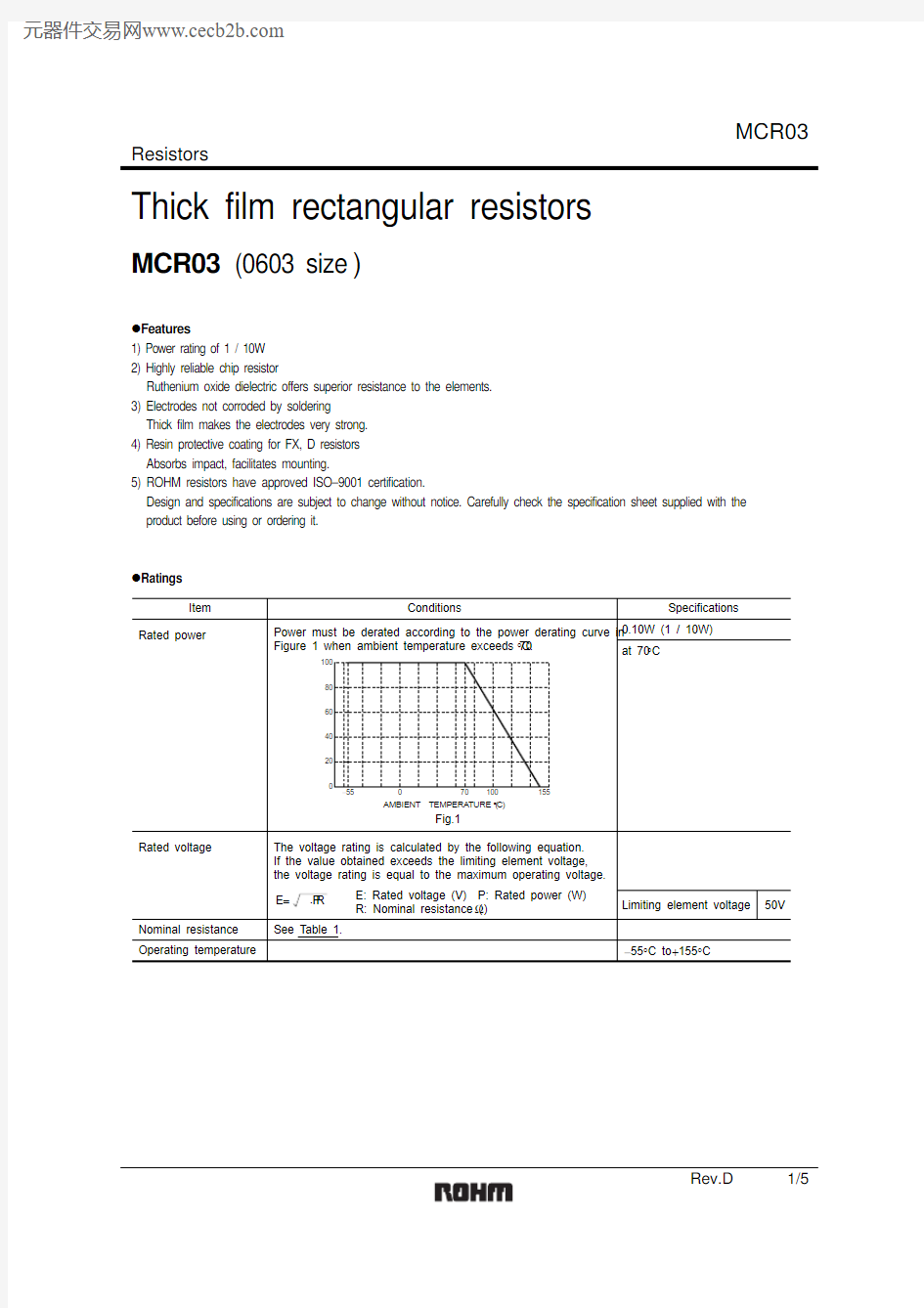
Rated power
Rated voltage
Operating temperature
Nominal resistance See Table 1.
Limiting element voltage
50V
Power must be derated according to the power derating curve in Figure 1 when ambient temperature exceeds 70°C.
The voltage rating is calculated by the following equation. If the value obtained exceeds the limiting element voltage, the voltage rating is equal to the maximum operating voltage.E: Rated voltage (V) P: Rated power (W) R: Nominal resistance (?)
E = P ×R
20406080
100?55070100155
AMBIENT TEMPERATURE (°C)
P O W E R L O A D (%)
Fig.1
Resistors
Rev.D 2/5
Max. 50m ?
1A
?55°C to +155°C
Jumper type Resistance Rated current
Operating temperature FX (±1%)J (±5%)D (±0.5%)
10 ≤ R ≤ 10M (E24,96)(E24)(E24)
±100±4001.0 ≤ R ≤ 9.1±20010 ≤ R ≤ 10M (E24,96)
(E24,96)
10 ≤ R ≤ 91
±100±50
100 ≤ R ≤ 1M Table 1
Resistance tolerance
Resistance range
(?)Resistance temperature coefficient
(ppm/°C)
z Before using components in circuits where they will be exposed to transients such as pulse loads (short–duration, high– level loads), be certain to evaluate the component in the mounted state. In addition, the reliability and performance of this component cannot be guaranteed if it is used with a steady state voltage that is greater than its rated voltage.
z Characteristics
Item
Test conditions (JIS C 5201-1)Resistor type Guaranteed value
Jumper type Resistance
Variation of resistance with temperature Solderability
Damp heat, steady state
Endurance at 70°C
Endurance
Rapid change of temperature
Bend strength of the end face plating
Resistance to solvent
Resistance to soldering heat Overload
± (2.0%+0.1?)
Max. 50m ?
± (1.0%+0.05?)± (3.0%+0.1?)
Max. 50m ?
Max. 100m ?
J : ±5%FX : ±1%D : ±0.5%
See Table.1
No remarkable abnormality on the appearance.A new uniform coating of minimum of 95% of the surface being immersed and no soldering damage.
Without mechanical damage such as breaks.
Max. 50m ?
JIS C 5201-1 4.5
JIS C 5201-1 4.8
Measurement : ?55 / +25 / +125°C JIS C 5201-1 4.18
Soldering condition : 260±5°C Duration of immersion : 10±1s.JIS C 5201-1 4.2440°C, 93%RH
Test time : 1,000h to 1,048h ± (3.0%+0.1?)
± (3.0%+0.1?)
± (1.0%+0.05?)
± (1.0%+0.05?)± (1.0%+0.05?)Max. 100m ?
Max. 100m ?
Max. 50m ?
Max. 50m ?Max. 50m ?
JIS C 5201-1 4.25.1
Rated voltage (current), 70°C 1.5h : ON ? 0.5h : OFF
Test time : 1,000h to 1,048h JIS C 5201-1 4.25.3155°C
Test time : 1,000h to 1,048h
JIS C 5201-1 4.29
23±5°C , Immersion cleaning, 5±0.5min.Solvent : 2-propanol JIS C 5201-1 4.19
Test temp. : ?55°C to +125°C 5cyc JIS C 5201-1 4.33
JIS C 5201-1 4.17
Rosin·Ethanol (25%WT)
Soldering condition : 235±5°C Duration of immersion : 2.0±0.5s.JIS C 5201-1 4.13
Rated voltage (current) ×2.5, 2s.Maximum overload voltage : 100V
Resistors
Rev.D 3/5
z Dimensions (Unit : mm)
z Packaging
Resistors
Rev.D 4/5
z Part designation
Reel (φ180) : JEITA ET-7200B
: Standard product
z Dimensions
RESISTANCE (?)L E N G T H (m m )
Fig.2 Dimensions (length)
RESISTANCE (?)W I D T H (m m )
Fig.3 Dimensions (width)
RESISTANCE (?)
T H I C K N E S S (m m )
Fig.4 Dimensions (thickness)
z
Electrical characteristics
RESISTANCE (?)D C R E S I S T A N C E (%)
???Fig.5 Resistance
?
????RESISTANCE (?)T E M P E R A T U R E C O E F I C I E N T (p p m / °C )
Fig.6 Variation of resistance with
temperature
?????RESISTANCE (?)
?R /R (%)
Fig.7 Overload
Resistors
Rev.D 5/5
????RESISTANCE (?)?R /R (%)
Fig.8 Resistance to soldering heat
????RESISTANCE (?)?R /R (%)
Fig.9 Rapid change of
temperature
????RESISTANCE (?)
?R /R (%)
Fig.10 Damp heat, steady state
????RESISTANCE (?)?R /R (%)
Fig.11 Endurance at 70°C
????RESISTANCE (?)?R /R (%)
Fig.12 Endurance
????RESISTANCE (?)
?R /R (%)
Fig.13 Resistance to solvents
????RESISTANCE (?)
?R /R (%)
Fig.14 Bend strength of
the end face plating
Appendix
About Export Control Order in Japan
Products described herein are the objects of controlled goods in Annex 1 (Item 16) of Export T rade Control
Order in Japan.
In case of export from Japan, please confirm if it applies to "objective" criteria or an "informed" (by MITI clause)
on the basis of "catch all controls for Non-Proliferation of Weapons of Mass Destruction.
Appendix1-Rev1.1