Improved time-varying mesh stiffness model of cracked spur gears

Improved time-varying mesh stiffness model of cracked spur gears
Hui Ma ?,Xu Pang,Ranjiao Feng,Jin Zeng,Bangchun Wen
School of Mechanical Engineering and Automation,Northeastern University,Shenyang,Liaoning 110819,PR China
a r t i c l e i n f o a
b s t r a
c t
Article history:
Received 4April 2015
Received in revised form 5June 2015Accepted 15June 2015
Available online 21June 2015Based on our previous work (Ma et al.,2014,Engineering Failure Analysis ,44,179–194),this paper presents an improved analytical model (IAM)for the time-varying mesh stiffness (TVMS)calculation of cracked spur gears.In the improved analytical model,the calculation error of TVMS under double-tooth engagement due to repeatedly considering the stiffness of the ?llet-foundation is revised,and the effects of reduction of ?llet-foundation stiffness of cracked gears and extended tooth contact (ETC)are also considered,which have a great in ?uence on TVMS,especially under the condition of large torques and crack levels.Moreover,the comparisons among the IAM,traditional analytical model (TAM)and ?nite element (FE)model are also carried out under different torques and crack depths.IAM is also veri ?ed by comparing TVMS and vibration responses obtained by FE model,which can be considered as a gauge to evaluate the calculation error.The results show that the maximum error of IAM is about 12.04%,however,that of TAM can be up to 32.73%.
?2015Elsevier Inc.All rights reserved.
Keywords:
Cracked spur gear
Time-varying mesh stiffness (TVMS)Extended tooth contact (ETC)Fillet-foundation stiffness Load sharing ratio (LSR)
1.Introduction
Time-varying mesh stiffness (TVMS)calculation is an important research area in cracked gear dynamics.Many researchers have developed various mathematical models to calculate TVMS and these models can be classi ?ed into four categories:?nite element (FE)method,analytical method (AM),analytical-FE method and experimental method.Among the four methods,FE method has widely been used for TVMS calculation because it has high accuracy and can simulate complicated gear structures.Based on FE method,TVMS can be calculated by applying a meshing force to the theoretical contact point of the gear pair [1–5]or by establishing contact elements between the meshing teeth [6–12].AM is based on the assumption of cantilever beam with variable cross-section,which has high computation ef ?ciency,however,its calculation accuracy is lower than that of FE https://www.wendangku.net/doc/3f10604845.html,MS calculation based on AM is widely used to vibration evaluation and model-based fault diagnosis of cracked gear system [1,2,4,5,13–33].Analytical-FE method combines the advantages of FE method (high accuracy)and AM (high computation ef ?ciency).Based on the analytical-FE method,Fernandez del Rincon et al.[34]presented a model for analyzing the in ?uences of cracks and pitting on the mesh stiffness,loaded transmission error (LTE)and load sharing ratio (LSR).TVMS evaluation by experiment is more dif ?cult,and related literatures are rare [35].Pandya and Parey [35]measured the TVMS variation of the gears and calculated the change of mesh stiffness for a pinion with a cracked tooth using the conventional photo-elasticity technique.
Based on the TVMS model for the healthy gear presented by Yang and Lin [36],many analytical models for calculating TVMS of cracked gear pairs were also improved to better simulate the actual conditions.Tian [13]and Wu [14]extended Yang's model by considering the effect of the shear energy.Simplifying a crack propagation path as a straight line,Wu et al.[15]presented a cracked tooth model to describe different crack levels.In Refs.[13,14,36],the gear tooth is assumed as a variable cross-section cantilever beam clamped on the base circle of the gear,which neglects the potential energy existing in the part between the base circle and the root
Engineering Failure Analysis 55(2015)271–287
?Corresponding author.Tel./fax:+862483684491.E-mail address:mahui_2007@https://www.wendangku.net/doc/3f10604845.html, (H.Ma).
https://www.wendangku.net/doc/3f10604845.html,/10.1016/j.engfailanal.2015.06.0071350-6307/?2015Elsevier Inc.All rights
reserved.
Contents lists available at ScienceDirect
Engineering Failure Analysis
journal homepage:w w w.e l s e v i e r.c o m /l oc a t e /e n g f a i l a n a
l
circle.In order to make up for this shortage,some researchers respectively presented different improved models,such as Chaari et al.[1],Wan et al.[18],Liang et al.[19],Ma et al.[5].Many researchers assume that the tooth crack is through the whole tooth width with a constant depth,which may be different from the real cracks under some conditions [5,13–15,19].Aiming at this de ?ciency,Chen and Shao [21]?rstly developed an analytical model for mesh stiffness calculation of a spur gear pair considering the tooth root crack propagating along both tooth width and crack depth.For the TVMS calculation of cracked gear pairs,a straight limiting line is usually used for stiffness reduction calculation;however,the straight limiting line may cause some errors under larger crack sizes [2].By revising limiting lines related to the tooth thickness,Mohammed et al.[2]presented a modi ?ed analytical method to calculate the TVMS of a cracked gear pair.Generally,the crack propagation path is usually assumed as a straight line;however,the real crack path is a slight curve extending from the tooth root in gears with a high backup ratio [37].In order to make up for this de ?ciency,based on the crack propagation paths determined using FRANC 2D (Fracture Analysis Code for 2Dimensions)[37],Pandya and Parey [31]presented a method to improve the traditional TVMS calculation model.Zhao et al.[27]also proposed a potential energy method for calculating the TVMS of the gear pair using a curved crack propagation path determined by FRANC 2D.Other improve-ments were also presented,for example,the effects of shaft misalignment and friction force on TVMS are considered in Ref.[33],and for planetary gear transmission,the in ?uence of ?exible ring gear rim on TVMS is taken into account in Ref.[24].
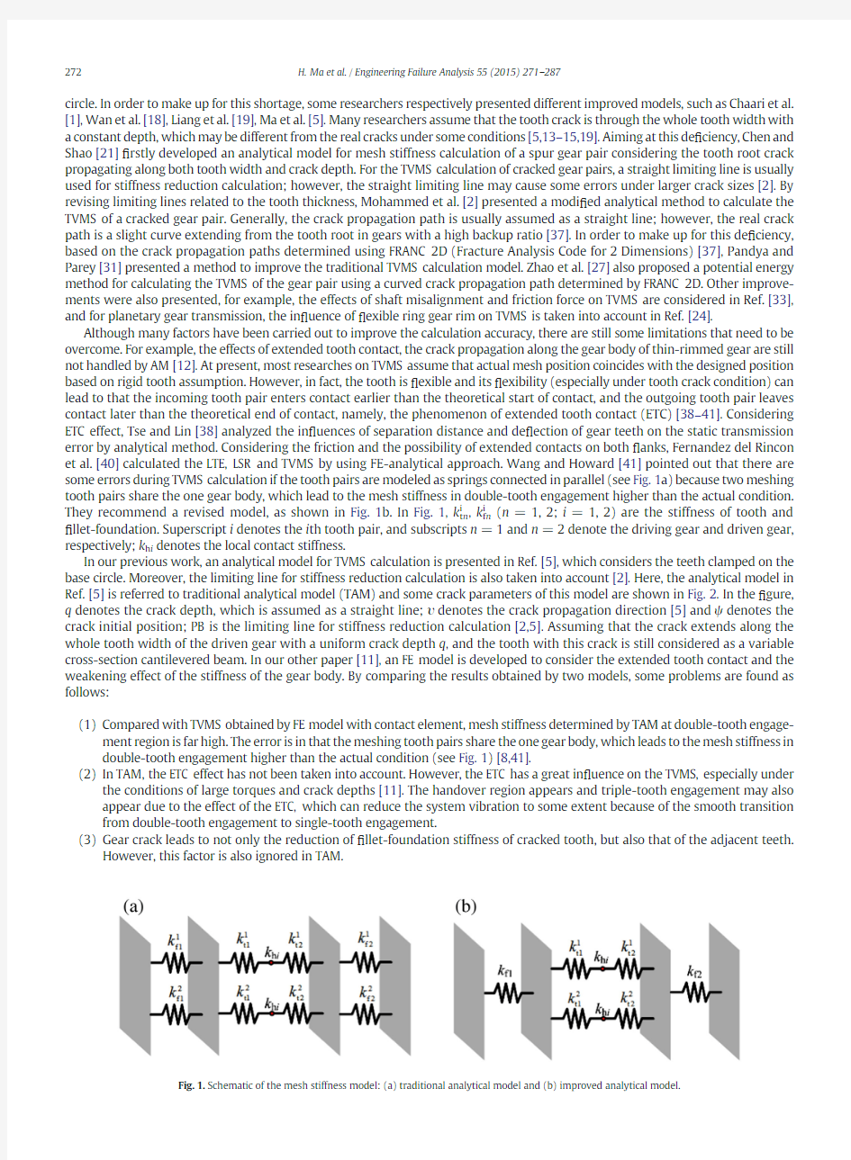
Although many factors have been carried out to improve the calculation accuracy,there are still some limitations that need to be overcome.For example,the effects of extended tooth contact,the crack propagation along the gear body of thin-rimmed gear are still not handled by AM [12].At present,most researches on TVMS assume that actual mesh position coincides with the designed position based on rigid tooth assumption.However,in fact,the tooth is ?exible and its ?exibility (especially under tooth crack condition)can lead to that the incoming tooth pair enters contact earlier than the theoretical start of contact,and the outgoing tooth pair leaves contact later than the theoretical end of contact,namely,the phenomenon of extended tooth contact (ETC)[38–41].Considering ETC effect,Tse and Lin [38]analyzed the in ?uences of separation distance and de ?ection of gear teeth on the static transmission error by analytical method.Considering the friction and the possibility of extended contacts on both ?anks,Fernandez del Rincon et al.[40]calculated the LTE,LSR and TVMS by using FE-analytical approach.Wang and Howard [41]pointed out that there are some errors during TVMS calculation if the tooth pairs are modeled as springs connected in parallel (see Fig.1a)because two meshing tooth pairs share the one gear body,which lead to the mesh stiffness in double-tooth engagement higher than the actual condition.
They recommend a revised model,as shown in Fig.1b.In Fig.1,k t n i ,k f n i
(n =1,2;i =1,2)are the stiffness of tooth and ?llet-foundation.Superscript i denotes the i th tooth pair,and subscripts n =1and n =2denote the driving gear and driven gear,respectively;k h i denotes the local contact stiffness.
In our previous work,an analytical model for TVMS calculation is presented in Ref.[5],which considers the teeth clamped on the base circle.Moreover,the limiting line for stiffness reduction calculation is also taken into account [2].Here,the analytical model in Ref.[5]is referred to traditional analytical model (TAM)and some crack parameters of this model are shown in Fig.2.In the ?gure,q denotes the crack depth,which is assumed as a straight line;υdenotes the crack propagation direction [5]and ψdenotes the crack initial position;PB is the limiting line for stiffness reduction calculation [2,5].Assuming that the crack extends along the whole tooth width of the driven gear with a uniform crack depth q ,and the tooth with this crack is still considered as a variable cross-section cantilevered beam.In our other paper [11],an FE model is developed to consider the extended tooth contact and the weakening effect of the stiffness of the gear body.By comparing the results obtained by two models,some problems are found as follows:
(1)Compared with TVMS obtained by FE model with contact element,mesh stiffness determined by TAM at double-tooth engage-ment region is far high.The error is in that the meshing tooth pairs share the one gear body,which leads to the mesh stiffness in double-tooth engagement higher than the actual condition (see Fig.1)[8,41].
(2)In TAM,the ETC effect has not been taken into account.However,the ETC has a great in ?uence on the TVMS,especially under
the conditions of large torques and crack depths [11].The handover region appears and triple-tooth engagement may also appear due to the effect of the ETC,which can reduce the system vibration to some extent because of the smooth transition from double-tooth engagement to single-tooth engagement.
(3)Gear crack leads to not only the reduction of ?llet-foundation stiffness of cracked tooth,but also that of the adjacent teeth.
However,this factor is also ignored in
TAM.
Fig.1.Schematic of the mesh stiffness model:(a)traditional analytical model and (b)improved analytical model.
272H.Ma et al./Engineering Failure Analysis 55(2015)271–287
In order to overcome the de ?ciency of TAM,and avoid the time-consuming iteration and the complicated contact processing of FE model,it is essential to develop an improved analytical model (IAM)for TVMS calculation.In this study,the IAM revises the error due to the meshing tooth pairs sharing the one gear body,and considers the effects of ETC and reduction of ?llet-foundation stiffness.Moreover,comparisons of TVMS and vibration responses obtained by TAM,IAM and FE model are also carried out under different torques and crack depths.Finally,IAM is validated by FE model,and the differences of three models are discussed as well.2.Improved analytical model for TVMS calculation of cracked gears
https://www.wendangku.net/doc/3f10604845.html,MS calculation of cracked gear pairs considering the effect of ?llet-foundation deformation
For TAM in Ref.[5],the total mesh stiffness of the gear pair in double-tooth engagement is modeled as springs connected in parallel (see Fig.1a).The stiffness is calculated by the direct summation of the mesh stiffness of tooth pairs:
k i
?1
1h i t1t1t1f1t1t2t1
f2
;k ?
X N i ?1
k i
;
e1T
where k i represents the mesh stiffness of the i th tooth pair,k is the total mesh stiffness,N denotes the number of meshing tooth pairs,
subscripts 1and 2denote the driving gear and driven gear.The stiffness of single tooth k t consists of the bending stiffness k b ,shear stiffness k s and axial compressive stiffness k a ,which can be expressed as:
k t ?1
1b t1s t1
a
:e2T
For the cracked tooth,only bending stiffness and shear stiffness change,then
k t ?1
1
b crack t1
s crack t
1a
;e3Twhere k b_crack and k s_crack denote bending and shear stiffness of cracked tooth [5].The local contact stiffness k h i of the i th tooth pair is written as [42]:
k h i ?
E 0:9L 0:8
F i 0:1
1:275
;F i ?F álsr i :e4T
where E is the Young's modulus,L is the tooth width,F is the total meshing force,F i is the meshing force of i th tooth pair,lsr i is the load sharing ratio.
For the IAM (see Fig.1b),the total mesh stiffness k can be expressed as:
k ?1
1λ1k f1t1k tooth t
1
λ2k f2
;k tooth ?
X N i ?1
k i
tooth ;
k i
tooth
?1 1k h i t1k t1t
1
k t2
;e5
T
Fig.2.Schematic of tooth crack propagation.
273
H.Ma et al./Engineering Failure Analysis 55(2015)271–287
in which λis correction coef ?cient of the ?llet-foundation stiffness [8],subscripts 1and 2denote the driving gear and driven gear respectively,k tooth i denotes the mesh stiffness caused by teeth deformation of i th tooth pair,and k tooth is the mesh stiffness due to teeth deformation of N tooth pairs in contact.
The correction coef ?cient λis determined by a 2D FE model of a gear with nine gear teeth,which is established by Plane183element under the plane strain condition (see Fig.3).Crack tip is simulated by 2D singular element.Without considering the ?exibility of tooth,the nodes of tooth are coupled with a Mass21element,which is established in the meshing position,and the displacement of Mass21element along the line of action is constrained.The inner ring nodes are coupled with the master node (geometric center of gear)and their radial displacements are constrained.The torque is equivalent to tangential forces,which are applied to the inner nodes of driving gear.Once the rotational deformation of ?llet-foundation is obtained by FE model,the torsional stiffness of ?llet-foundation can be determined [8].Parameters of the studied spur gear pair are listed in Table 1.Based on FE model (see Fig.3),?llet-foundation stiffness for gear with crack depths of q =0,1,2,3mm is obtained,as is shown in Fig.4.In the ?gure,the underpainting zone denotes the theoretical double-tooth engagement zone.It can be found that ?llet-foundation stiffness de-creases due to the presence of crack.And except for theoretical zone of crack tooth contact (TZCTC),other mesh cycles are also affect-ed.Owing to high torque or contact ratio,triple-tooth may occur in theoretical single-tooth contact zone or theoretical double-tooth contact zone [38].Assuming a triple-tooth engagement takes place in the total mesh cycle,?llet-foundation stiffness in triple-tooth contact is obtained,as shown in Fig.4b.Moments A,B,C and D are selected to evaluate the increase or decrease of ?llet-foundation stiffness relative to that of healthy gear in single-tooth engagement,which can be de ?ned as:
r k fA ?
k fA ?k fB health k fB health ?100%;r k fB ?k fB ?k fB health k fB health ?100%;r k fC k fC ?k fB health fB health 100%;r k fD ?k fD ?k fB health
k fB health
?100%;e6T
where k fA ,k fB ,k fC and k fD represent the ?llet-foundation stiffness corresponding to moments A (double-tooth engagement),B
(single-tooth engagement),C (triple-tooth engagement in theoretical double-tooth engagement)and D (triple-tooth engagement in theoretical single-tooth engagement).k fB_health denotes ?llet-foundation stiffness of the healthy gear.For IAM,the ?llet-foundation stiffness can be obtained by ?llet-foundation stiffness in single-tooth engagement [43]multiplying correction coef ?cient,which is de ?ned as:
λ?1tr k f :
e7T
In this paper,four mesh cycles are investigated,and r k f is determined for the gear pair of our research (see Table 2).Fig.5presents the ?llet-foundation stiffness corresponding to moments A,B,C and D of healthy gear under different torques,which indicates that the ?llet-foundation stiffness is not affected by the torques.Hence,the correction coef ?cient
does not change under different torques.
Fig.3.FE model for calculating ?llet-foundation stiffness:(a)single-tooth engagement,(b)double-tooth engagement,and (c)triple-tooth engagement.
274H.Ma et al./Engineering Failure Analysis 55(2015)271–287
https://www.wendangku.net/doc/3f10604845.html,MS calculation of cracked gear considering the effect of ETC
In this section,considering the effect of ETC,an improved analytical model for TVMS calculation is proposed based on Ref.[5].Fig.6illustrates three meshing tooth pairs.It is assumed that crack appears at tooth pair 2of the driven gear.In the ?gure,the black solid line and dotted line represent the actual gear pro ?le and theoretical gear pro ?le,respectively.AB and CD denote the theoretical double-tooth contact zone,and BC denotes the theoretical single-tooth contact zone.S a and S r are the separation distances of pairs 3and 1along the line of action,respectively.
When tooth pairs 1and 2are in contact simultaneously,the static transmission error E r without considering the effect of ?llet-foundation deformation and meshing force F at meshing point j can be expressed as [38]:
E 1r j
?E 1d1 j
tE 1d2 j
tE 1p1 j
tE 1p2 j
tE 1s1 j
tE 1
s2 j
;
e8
T
Fig.4.Fillet-foundation stiffness:(a)?llet-foundation stiffness in single-and double-tooth engagements and (b)?llet-foundation stiffness in triple-tooth engagement.
Table 1
Parameters of the studied spur gear pair.Number of teeth of driving gear Number of teeth of driven gear Young's modulus E (GPa)Poisson's ratio v Module m (mm)55
75
212
0.289
2
Addendum coef ?cient h a ?Tip clearance coef ?cient c ?Tooth width L (mm)Pressure angle α(°)Hub bore radius r int (mm)1
0.25
20
20
17.5
Note:Other parameters of driving gear and driven gear are the same except for the number of the teeth.
275
H.Ma et al./Engineering Failure Analysis 55(2015)271–287
E 2r j
?E 2d1 j
tE 2d2 j
tE 2p1 j
tE 2
p2 j
;
e9T
F ?F 1j tF 2
j ;
e10T
where E d ,E p and E s represent the tooth de ?ection,tooth pro ?le error and tooth spacing error,respectively.It is worth noting that E p is positive if material is removed from surface of contact point,otherwise,it is negative.While the tooth spacing of driven gear is less than base pitch P b or the tooth spacing of driving gear is larger than P b ,E s is positive.Superscripts 1,2and 3denote tooth pairs 1,2and 3(see Fig.6),respectively.
Based on Eqs.(8)and (9),Eq.(10)can be further written as:
F ?
E 1
r
j
?E 1p j
?E 1s
j
Q j
t
E 2
r
j
?E 2p
j
Q j
;e11T
here (E d )j =(E d1)j +(E d2)j ,(E p )j =(E p1)j +(E p2)j ,(E s )j =(E s1)j +(E s2)j and Q i denotes the teeth deformation of the i th tooth pair
under unit force,which can be expressed as
Q i ?
1k h i t1k b1t1k s1t1k a1t1k b2t1k s2t1k a2;for healthy tooth pair ;1k h i t1k b1t1k s1t1k a1t1k b crack t1k s crack t1k a2
;for cracked tooth pair :8>><>>:
e12T
Table 2
The increase or decrease percentage for ?llet-foundation stiffness of driven gear.q (mm)
Mesh cycle 3Mesh cycle 4r k fB (%)
r k fA (%)r k fC (%)r k fD (%)r k fB (%)r k fA (%)r k fC (%)r k fD (%)008.3115.3921.4208.3115.3921.421?0.208.1713.1919.91?7.80 5.9113.8720.122?0.917.7410.3918.04?18.59 1.9112.4318.513?2.38 6.87
8.14
16.65
?29.17?1.21
11.21
17.38
q (mm)
Mesh cycle 5Mesh cycle 6r k fB (%)
r k fA (%)r k fC (%)r k fD (%)r k fB (%)r k fA (%)r k fC (%)r k fD (%)008.3115.3921.4208.3115.3921.421?0.54 4.5413.6320.92?0.137.8515.3021.032?1.89?0.5511.1220.12?0.38 6.7314.0919.903
?3.36
?3.22
9.05
19.33
?0.76
5.47
13.06
19.07
Note:For the driving gear,r kfB =0,r k fA =11.96%,r k fC =22.69,r k fD =40.52%,which are not affected by the crack
depth.
Fig.5.Fillet-foundation stiffness under different torques (a)driving gear and (b)driven gear.
276H.Ma et al./Engineering Failure Analysis 55(2015)271–287
The static transmission errors of tooth pairs in mesh are the same,and the static transmission error can be determined by solving Eq.(11).
E 2r j ?Q 2j E 1p j tQ 2j E 1s j tQ 1j E 2p j
tQ 1j Q 2
j F Q j j
:e13T
Thus,the stiffness caused by tooth deformation during double-tooth engagement can be calculated by:
k tooth
?F E r ?E p
;where E i p ?min E 1p ;E 2
p e14T
here,i denotes the i th tooth pair.
The total mesh stiffness can be obtained by Eq.(5).In addition,the mesh stiffness of single-tooth pair is a function of tooth contact deformation E d and meshing position j ,which can be expressed as:
k ?
k i
;E i
d N 0
0;
E i
d ≤0
(:e15T
The loaded transmission error of gear considering the effect of ?llet-foundation deformation can be written as:
E gear r
?F k
tE i p ;where E i p ?min E 1p ;E 2
p ;e16T
here,E p i =min(E p 1,E p 2,E p 3
)when triple-tooth engagement
occurs.
Fig.6.Schematic of the meshing
gear.
Fig.7.Loaded transmission errors considering the effect of ETC:(a)occurrence of ETC in the single-tooth contact zone without overlap,(b)occurrence of ETC in the single-tooth contact zone with overlap,and (c)occurrence of ETC in the double-tooth contact zone with overlap.
277
H.Ma et al./Engineering Failure Analysis 55(2015)271–287
Fig.7shows three cases of LTE in?uenced by extended tooth contact.In the?gure,the solid line and dotted line denote the conditions considering the effect of ETC and without considering this effect,respectively.And points B and C represent the positions of theoretical start of contact and theoretical end of contact,points B′and C′denote the positions of actual start of contact and actual end of contact.Assuming that tooth pair2meshes at point B,tooth pair1is leaving contact in theory(see Fig.6).However,due to the effect of ETC,tooth pair1is still in mesh when S r≤E r gear(see Fig.7a)and does not leave contact until S r N E r gear.Similarly,tooth pair3
enters contact ahead of theoretical start of contact when S a≤E r gear.When S r≤E r gear and S a≤E r gear,three tooth pairs are in
mesh
https://www.wendangku.net/doc/3f10604845.html,MS calculation schematic considering the effect of ETC. 278H.Ma et al./Engineering Failure Analysis55(2015)271–287
simultaneously.And only tooth pair 2is in mesh when S r N E r gear and S a N E r
gear .Therefore,based on Eq.(11),meshing force F for single-tooth contact (tooth pair 2),double-tooth contact (tooth pairs 1and 2,2and 3)and triple-tooth contact (tooth pairs 1,2and 3)can be calculated by:
F ?E 2r
j Q j ;S r N E gear r and S a N E gear r ;E 1r j ?E 1p j ?E 1s j ?S 1r j Q j tE 2r j ?E 2p j Q
j ;S r ≤E gear r ;E 2r j ?E 2p j Q j tE 3r j ?E 3p j ?E 3s j ?S 3a
j Q j ;S a ≤E gear r ;E 1r j ?E 1p j ?E 1s j ?S 1r j Q j
tE 2r j ?E 2p j Q j
tE 3r j ?E 3p j ?E 3s j ?S 3a j Q
j
;S r ≤E gear
r
and S a ≤E gear
r
:
8>>>>>>>>>>>>>>>>>>><>>>>>>>>>>>>>>>>>>>:e17T
Solving Eq.(17),the static transmission error is obtained by
E 2
r j ?F Q 2j ;S r N E gear r and S a N E gear r Q 2j E 1p j tQ 2j E 1s j tQ 2j S 1r j tQ 1j E 2p j tQ 1j Q 2j F Q 1j tQ 2j ;S r ≤E gear r Q 3j E 2p j tQ 2j E 3p j tQ 2j E 3s j tQ 2j S 3a j tQ 2j Q 3j F Q j j ;S a ≤E gear r Q 1j Q 2j E 3p j tQ 1j Q 2j E 3s j tQ 1j Q 2j S 3a j tQ 1j Q 3j E 2p j Q j Q j j Q j j Q j tQ 2j Q 3j E 1p j tQ 2j Q 3j E 1s j tQ 2j Q 3j S 1r j tQ 1j Q 2j Q 3j F Q j Q j tQ j Q j tQ j Q j
;S r ≤E gear r and S a ≤E gear r :8
>>>>>>>>>>>>>>>>>>>>>>>><>>>>>>>>>>>>>>>>>>>>>>>>::e18T
Finally,the stiffness of teeth and the total mesh stiffness can be determined by Eqs.(14)and (5),respectively.
Based on Ref.[44],load sharing ratios indicating the ratio of the meshing force of one tooth pair to the total meshing force for the healthy gear and cracked gear can be calculated by:
lsr 1?F 1F ?
1;S r N E gear
r
and S a N E gear
r ;
E 1r j ?E 1p j ?E 1s j ?S 1r j FQ
1
j
;S r ≤E gear r
;0;S a ≤E gear
r ;
E 1r j ?E 1p j ?E 1s j ?S 1r j FQ 1
j
;S r ≤E gear
r
and S a ≤E gear
r
8>>>>>>>>>><>>>>>>>>>>:e19T
lsr 2?F 2
F ?0;S r N E gear r and S a N E gear r ;E 2r j ?E 2p j FQ 2j ;S r ≤E gear r ;E 2r j ?E 2p j FQ 2j ;S a ≤E gear r ;E 2r j ?E 2p j FQ 2
j ;S r ≤E gear r and S a ≤E gear r 8>>>>>>>>>>>>>>><>>>>>>>>>>>>>>>:e20T
lsr 3?1?lsr 1?lsr 2
e21T
where lsr is the load sharing ratio and subscripts 1,2and 3denote the tooth pairs 1,2and 3respectively.The schematic for calculating TVMS is shown in Fig.8.
279
H.Ma et al./Engineering Failure Analysis 55(2015)271–287
3.Validation and discussion
In this paper,the schematic of tooth crack propagation is presented in Fig.2.And crack parameters are assumed as follows:q =1,2and 3mm,υ=45°,ψ=35°.A 2D FE model of a gear pair with healthy tooth and cracked tooth developed in Ref.[11]is also adopted to verify IAM,Additionally,an FE model of a geared rotor system established in our previous paper [11]is adopted to compare the dif-ference of vibration responses by TAM,IAM and FE model.A dynamic model of a spur gear pair is coupled with two shafts,as is shown in Fig.9.Motion equations of the whole geared rotor system can be written in matrix form as follows:
M €u
tC tG eTu
tKu ?F u e22T
where M ,K ,C ,G are the mass,stiffness,damping and gyroscopic matrices of the global system;u and F u denote the displacement and
external force vectors of the global system.All these matrices and vectors can be obtained in Ref.[11].The parameters of the system are listed in Fig.9and Table 3.Both shafts 1and 2are divided into 13elements,gears 1and 2are located at nodes 8and 22,respec-tively (see Fig.9
).
Fig.10.Load sharing ratio under different torques:(a)IAM and (b)FE method.
Table 3
Parameters of the gears and bearings.Gear parameters Gears I x =I y
(kg ·mm 2)I z
(kg ·mm 2)m (kg)Gears I x =I y
(kg ·mm 2)I z
(kg ·mm 2)m (kg)1
1247.99
4069.31
1.53
2
2338.84
7892.28
3.01
Bearing parameters Bearings k xx (MN/m)k yy (MN/m)k zz (MN/m)k θx θx (MN ?m/rad)k θy θy (MN ?m/rad)All
200
200
100
0.1
0.1
281
H.Ma et al./Engineering Failure Analysis 55(2015)271–287
3.1.Validation of load sharing ratio
Based on FE method and IAM,load sharing ratio of a healthy gear pair under different torques of T 1=10,60,100,150,300Nm are obtained (see Fig.10).Load sharing ratios are smooth in handover region between double-tooth engagement and single-tooth engagement due to ?exibility of gear.For T 1=150and 300Nm,triple-tooth engagement appears.LSR for the cracked gear pair with crack depths of q =0,1,2,3mm under T 1=60Nm are displayed in Fig.11.It can be observed that the load sharing ratios of tooth pairs 1and 3increase with the growth of crack depths.LSR of tooth pair 2(tooth with crack)becomes small,which indicates that the carrying capacity of cracked tooth is weakened.And the results obtained from IAM shows agreement with those of FE method.3.2.Effect of local contact stiffness
In this part,effects of the local contact stiffness k h i =πEL /[4(1?ν2)][5]and k h i =E 0.9L 0.8F i 0.1[42]on TVMS are investigated.Based on TAM and IAM with different equations of k h i and FE method,TVMS of gear pairs under torques of 10,100,150and 300Nm are shown in https://www.wendangku.net/doc/3f10604845.html,pared with FE method,TVMS obtained by TAM is much greater,especially when TAM uses the equation of k h i =πEL /[4(1?ν2)].No matter which equation of k h i is adopted TVMS of gear pairs under IAM has a better performance than those under TAM.At the same time,it can be seen that methods with k h i =E 0.9L 0.8F i 0.1agree well with FE model when the torque is between 0and 300N/m.Therefore,in this paper,IAM using k h i =E 0.9L 0.8F i 0.1is adopted.3.3.Effect of crack depth
Based on TAM,FE method and IAM,TVMS of gear pair with crack depth of q =0,1,2,3mm under T =60Nm is obtained (see Fig.13).For the three models,the stiffness at moments A (double-tooth engagement)and B (single-tooth engagement)shown in Fig.13is listed in Table 4.Vibration responses under q =1and 3mm,T =60Nm are displayed in Fig.14.These ?gures show the following phenomena.
(1)In handover region between the double-tooth engagement and single-tooth engagement,TVMS of IAM and FE method
becomes smooth instead of a jump (see Fig.13).Compared with TVMS obtained by TAM,mesh stiffness of cracked gear obtained by FE method and IAM both decreases besides the theoretical zone of cracked tooth contact (see the zoomed plot),which is due to the reduction of the ?llet-foundation stiffness.Additionally,it can be observed that the results of IAM agree well with those of FE model.The maximum error at single-tooth engagement point is up to 7.40%under q =0mm and
the
Fig.11.Load sharing ratio under different crack depths (T 1=60Nm):(a)IAM and (b)FE method.
282H.Ma et al./Engineering Failure Analysis 55(2015)271–287
maximum error at double-tooth engagement is 5.60%under q =3mm (see Table 4).However,for the results of TAM,maxi-mum errors at single-tooth and double-tooth engagements are 8.03%and 28.81%,respectively.
(2)The waveform of acceleration shows that the vibration response of TAM is far greater than those of IAM and FE model.And the
vibration of IAM shows a good agreement with that of FE model.
3.4.Effect of torque
For the gear pair with tooth root crack,TVMS with crack depths of q =3mm is obtained under T =10,100,150and 300Nm,as shown in Fig.15.Vibration responses under q =3mm,T 1=10and 100Nm are displayed in Fig.16.With the increasing torque,the extended tooth contact becomes obvious.Under T 1=100,150and 300Nm,three tooth contact zones appear (see Fig.15b,c and d).For the results of TAM,the maximum error at single-tooth engagement is up to 32.73%under T 1=300Nm,and the maximum error at double-tooth engagement is 25.32%under T 1=10Nm (see Table 5).However,for the results of IAM,the maximum errors at single-tooth engagement and double-tooth engagement are respectively 12.04%and 6.19%.Compared with the results of TAM,it is clear that the changing trend of IAM agrees well with that of FE model.Similarly,the waveform of acceleration indicates the vibration response of IAM agrees well with that of FE model.In addition,it takes 30s to calculate the TVMS in one mesh cycle by IAM,which will spend an hour to obtain the TVMS by FE model at the same condition.Therefore,the improved analytical model is not only accurate but also ef ?cient to determine the mesh stiffness.4.Conclusions
In this study,an improved analytical model (IAM)for the time-varying mesh stiffness (TVMS)calculation of cracked gears is proposed.The improved analytical model revises the calculation error of TVMS under double-tooth engagement due to repeatedly considering the stiffness of the ?llet-foundation,and considers the effects of the extended tooth contact,which has a great in ?uence on TVMS,especially under large torques and crack levels.The IAM is also veri ?ed by comparing the TVMS and vibration responses obtained by IAM,traditional analytical model (TAM)and ?nite element (FE)model.Taking the results of FE model as reference,the calculation error of TVMS under double-tooth engagement is obviously reduced based on IAM.The maximum error by IAM
is
https://www.wendangku.net/doc/3f10604845.html,parison of mesh stiffness under different torques:(a)T 1=10Nm,(b)T 1=100Nm,(c)T 1=150Nm,(d)T 1=300Nm.
283
H.Ma et al./Engineering Failure Analysis 55(2015)271–287
about 12.04%;however,the error is up to 32.73%by TAM.In addition,the IAM can also simulate the triple-tooth engagement under large torques and crack depths,which cannot be handled by TAM.
Nomenclature c ?tip clearance coef ?cient C damping matrix of the global system E Young's modulus
E d i ,E p i and E s i tooth de ?ection,tooth pro ?le error and tooth spacing error E r
i
loaded static transmission error of the i th tooth pair without considering the effect of ?llet-foundation deformation E r
gear
loaded static transmission error considering the effect of ?llet-foundation deformation F
i
meshing force of the i th tooth pair F total meshing force
F u
external force vectors of the global system G gyroscopic matrix of the global system h a ?addendum coef ?cient i i th tooth pair j meshing position at the involute
curve
https://www.wendangku.net/doc/3f10604845.html,MS under T 1=60Nm (a)TAM,(b)FE method,and (c)IAM.
Table 4
Stiffness comparison of three models under different crack depths.q (mm)
FE method TAM IAM k A (MN/m)
k B (MN/m)k A (MN/m)Error (%)k B (MN/m)Error (%)k A (MN/m)Error (%)k B (MN/m)Error (%)0290.9222.9374.728.81205.0?8.03283.1?2.68206.4?7.401281.5210.0362.428.74199.1?5.19274.8?2.38201.0?4.292272.3200.1345.626.92190.8?4.65262.9?3.45195.1?2.503
264.4
193.2
322.0
21.79
178.2
?7.76
249.6
?5.60
187.5
?2.95
284H.Ma et al./Engineering Failure Analysis 55(2015)271–287
k a ,k b ,k h ,k f ,k s axial compressive,bending,local contact,?llet foundation and shear stiffness k b_crack ,k s_crack bending and shear stiffness of cracked tooth
k fA ,k fB ,k fC and k fD ?llet-foundation stiffness corresponding to moments A,B,C and D k fB_health ?llet-foundation stiffness of healthy gear corresponding to moment B
k t
stiffness of single tooth k tooth
i
mesh stiffness due to teeth deformation of the i th tooth
pair https://www.wendangku.net/doc/3f10604845.html,MS with q =3mm under different torque conditions:(a)T 1=10Nm,(b)T 1=100Nm,(c)T 1=150Nm,(d)T 1=300
Nm.
Fig.14.Time-domain waveforms for gear with different crack depths (a)q =1mm,T =60Nm,and (b)q =3mm,T =60Nm.
285
H.Ma et al./Engineering Failure Analysis 55(2015)271–287
k tooth total mesh stiffness due to teeth deformation of N tooth pairs k i mesh stiffness of the i th tooth pair k total mesh stiffness of the gear pair K stiffness matrix of the global system L tooth width
lsr load sharing ratio m module
M mass matrix of the global system
n n =1,2corresponding to the driving gear and driven gear N number of meshing tooth pairs P b
base pitch
q ,υ,ψcrack depth,crack propagation direction and crack initial position Q i tooth deformation of the i th tooth pair under unit force
r kf increase percentage of ?llet-foundation stiffness in double-tooth engagement relative to that in single-tooth engagement r int hub bore radius
S a ,S r separation distance of the coming tooth pair and leaving tooth pair,respectively T 1,T 2torques of the driving and driven gears u displacement vector of the global system αpressure angle
λ1,λ2correction coef ?cient of the ?llet-foundation stiffness for driving gear and driven gear ρdensity
v Poisson's ratio
Acknowledgments
This project is ?nancially supported by Program for New Century Excellent Talents in University (Grant No.NCET-11-0078),the Fundamental Research Funds for the Central Universities (Grant Nos.N130403006and N140301001)and the Joint Funds of the National Natural Science Foundation and the Civil Aviation Administration of China (Grant No.U1433109).We also thank the anonymous reviewers for their valuable comments.
Table 5
Stiffness comparison of three models under different torques.T 1(Nm)
FE method TAM IAM k A (MN/m)
k B (MN/m)k A (MN/m)Error (%)k B (MN/m)Error (%)k A (MN/m)Error (%)k B (MN/m)Error (%)10249.6175.3312.825.32172.2?1.77243.3?2.52154.2?12.04
100268.5218.2324.620.89179.7?17.64251.3?6.41218.60.18150267.6240.7327.422.35180.3?25.09252.6?5.61241.60.37300
271.5
271.6
329.9
21.51
182.7
?32.73
254.7
?6.19
270.1
?
0.55
Fig.16.Time-domain waveforms for gear with crack depth:(a)q =3mm,T 1=10Nm,and (b)q =3mm,T 1=150Nm.
286H.Ma et al./Engineering Failure Analysis 55(2015)271–287
References
[1] F.Chaari,T.Fakhfakh,M.Haddar,Analytical modelling of spur gear tooth crack and influence on gearmesh stiffness,Eur.J.Mech.A Solids 28(2009)461–468.[2]O.D.Mohammed,M.Rantatalo,J.Aidanpaa,Improving mesh stiffness calculation of cracked gears for the purpose of vibration-based fault analysis,Eng.Fail.Anal.
34(2013)235–251.
[3]S.Zouari,M.Maatar,T.Fakhfakh,et al.,Three-dimensional analyses by finite element method of a spur gear:effect of cracks in the teeth foot on the mesh
stiffness,J.Fail.Anal.Prev.7(2007)475–481.
[4]H.Ma,R.Z.Song,X.Pang,et al.,Fault feature analysis of a cracked gear coupled rotor system,Mathematical Problems in Engineering,Volume 20142014.[Article
ID 832192,22pages].
[5]H.Ma,R.Z.Song,X.Pang,et al.,Time-varying mesh stiffness calculation of cracked spur gears,Eng.Fail.Anal.44(2014)179–194.
[6]I.Howard,S.X.Jia,J.D.Wang,The dynamic modeling of a spur gear in mesh including friction and a crack,Mech.Syst.Signal Process.15(2001)831–853.
[7]S.Jia,I.Howard,Comparison of localised spalling and crack damage from dynamic modelling of spur gear vibrations,Mech.Syst.Signal Process.20(2006)
332–349.
[8]J.D.Wang,Numerical and experimental analysis of spur gears in meshPh.D.Thesis Curtin University of Technology,Australia,2003.
[9]H.Ma,J.Yang,R.Z.Song,et al.,Effects of tip relief on vibration responses of a geared rotor system,Proc.Inst.Mech.Eng.C J.Mech.Eng.Sci.228(2014)1132–1154.[10]H.Ma,X.Pang,Q.B.Wang,et al.,Corrigendum to:effects of tip relief on vibration responses of a geared rotor system,Proc.Inst.Mech.Eng.C J.Mech.Eng.Sci.
(2014)https://www.wendangku.net/doc/3f10604845.html,/10.1177/0954406214563963.
[11]H.Ma,X.Pang,R.J.Feng,et al.,Fault features analysis of cracked gear considering the effects of the extended tooth contact,Eng.Fail.Anal.48(2015)105–120.[12]H.Ma,X.Pang,J.Zeng,et al.,Effects of gear crack propagation paths on vibration responses of the perforated gear system,Mech.Syst.Signal Process.(62-63)
(2015)113–128.
[13]X.H.Tian,Dynamic simulation for system response of gearbox including localized gear faultsM.S.thesis University of Alberta,Edmonton,2004.[14]S.Y.Wu,Gearbox dynamic simulation and estimation of fault growthM.S.thesis University of Alberta,Edmonton,2007.
[15]S.Y.Wu,M.J.Zuo,A.Parey,Simulation of spur gear dynamics and estimation of fault growth,J.Sound Vib.317(2008)608–624.
[16] F.B.Zhang,L.G.Cai,F.Wang,et al.,Study on calculation methods for sampling frequency of acceleration signals in gear system,Volume 2013,2013.(Article ID
462401,13pages).
[17]R.Ma,Y.S.Chen,Research on the dynamic mechanism of the gear system with local crack and spalling failure,Eng.Fail.Anal.26(2012)12–20.
[18]Z.G.Wan,H.R.Cao,Y.Y.Zi,et al.,An improved time-varying mesh stiffness algorithm and dynamic modeling of gear-rotor system with tooth root crack,Eng.Fail.
Anal.42(2014)157–177.
[19]X.H.Liang,M.J.Zuo,M.Pandey,Analytically evaluating the influence of crack on the mesh stiffness of a planetary gear set,Mech.Mach.Theory 76(2014)20–38.[20]X.H.Liang,M.J.Zuo,M.R.Hoseini,Vibration signal modeling of a planetary gear set for tooth crack detection,Eng.Fail.Anal.48(2015)185–200.
[21]Z.G.Chen,Y.M.Shao,Dynamic simulation of spur gear with tooth root crack propagating along tooth width and crack depth,Eng.Fail.Anal.18(2011)
2149–2164.
[22]Z.G.Chen,Y.M.Shao,Dynamic features of a planetary gear system with tooth crack under different sizes and inclination angles,Trans.ASME J.Vib.Acoust.135
(2013)[031004-1-12].
[23]Z.G.Chen,Y.M.Shao,Dynamic simulation of planetary gear with tooth root crack in ring gear,Eng.Fail.Anal.31(2013)8–18.
[24]Z.G.Chen,Z.F.Zhu,Y.M.Shao,Fault feature analysis of planetary gear system with tooth root crack and flexible ring gear rim,Eng.Fail.Anal.49(2015)92–103.[25]O.D.Mohammed,M.Rantatalo,J.Aidanpaa,et al.,Vibration signal analysis for gear fault diagnosis with various crack progression scenarios,Mech.Syst.Signal
Process.41(2013)176–195.
[26]O.D.Mohammed,M.Rantatalo,J.-O.Aidanp??,Dynamic modelling of a one-stage spur gear system and vibration-based tooth crack detection analysis,Mech.
Syst.Signal Process.54–55(2015)293–305.
[27] F.Q.Zhao,Z.G.Tian,Y.Zeng,Uncertainty quantification in gear remaining useful life prediction through an integrated prognostics method,IEEE Trans.Reliab.62
(2013)146–159.
[28]Y.M.Shao,Z.G.Chen,Dynamic features of planetary gear set with tooth plastic inclination deformation due to tooth root crack,Nonlinear Dyn.74(2013)
1253–1266.
[29]X.J.Zhou,Y.M.Shao,Y.G.Lei,et al.,Time-varying meshing stiffness calculation and vibration analysis for a 16DOF dynamic model with linear crack growth in a
pinion,ASME J.of Vib.Acoust.134(2012)011011.1–011011.11.
[30]Y.Pandya,A.Parey,Simulation of crack propagation in spur gear tooth for different gear parameter and its influence on mesh stiffness,Eng.Fail.Anal.30(2013)
124–137.
[31]Y.Pandya,A.Parey,Failure path based modified gear mesh stiffness for spur gear pair with tooth root crack,Eng.Fail.Anal.27(2013)286–296.[32]Y.Pandya,A.Parey,Crack behavior in a high contact ratio spur gear tooth and its effect on mesh stiffness,Eng.Fail.Anal.34(2013)69–78.
[33] A.Saxena,A.Parey,M.Chouksey,Effect of shaft misalignment and friction force on time varying mesh stiffness of spur gear pair,Eng.Fail.Anal.49(2015)79–91.[34] A.Fernandez del Rincon,F.Viadero,M.Iglesias,et al.,Effect of cracks and pitting defects on gear meshing,Proc.Inst.Mech.Eng.C J.Mech.Eng.Sci.226(2012)
2805–2815.
[35]Y.Pandya,A.Parey,Experimental investigation of spur gear tooth mesh stiffness in the presence of crack using photoelasticity technique,Eng.Fail.Anal.34
(2013)488–500.
[36] D.C.H.Yang,J.Y.Lin,Hertzian damping,tooth friction and bending elasticity in gear impact dynamics,J.Mech.Transm.Autom.Des.109(1987)189–196.[37] D.G.Lewicki,R.Ballarini,Effect of rim thickness on gear crack propagation path,J.Mech.Des.119(1997)88–95.
[38] D.K.Tse,H.H.Lin,Separation distance and static transmission error of involute spur gears,28th Joint Propulsion Conference and Exhibit,Nashville,America,1992.[39]Q.Han,J.Wang,Q.Li,Analysis of parametric stability for a spur gear pair system considering the effect of extended tooth contact,Proc.Inst.Mech.Eng.C J.Mech.
Eng.Sci.223(2009)1787–1797.
[40] A.Fernandez del Rincon,F.Viadero,M.Iglesias,et al.,A model for the study of meshing stiffness in spur gear transmissions,Mech.Mach.Theory 61(2013)30–58.[41]J.Wang,I.Howard,The torsional stiffness of involute spur gears,Proc.Inst.Mech.Eng.C J.Mech.Eng.Sci.218(2004)131–142.[42]R.W.Cornell,Compliance and stress sensitivity of spur gear teeth,J.Mech.Des.103(2)(1981)447–459.
[43]P.Sainsot,P.Velex,O.Duverger,Contribution of gear body to tooth deflections —a new bidimensional analytical formula,J.Mech.Des.126(4)(2014)748–752.[44]Z.G.Chen,Y.M.Shao,Mesh stiffness calculation of a spur gear pair with tooth profile modification and tooth root crack,Mech.Mach.Theory 62(2013)63–74.
287
H.Ma et al./Engineering Failure Analysis 55(2015)271–287