strong coupling superconductor
coupled system by applying pulses of varying length.In Fig.3b,Rabi oscillations are shown for the j00.to j11.transition.When the microwave frequency is detuned from resonance,the Rabi oscil-lations are accelerated(bottom four curves,to be compared with the?fth curve).After a p pulse which prepares the system in the j10.state,these oscillations are suppressed(second curve in Fig.3b).After a2p pulse they are revived(?rst curve in Fig.3b). In the case of Fig.3c,the qubit is?rst excited onto the j10.state by a p pulse,and a second pulse in resonance with the red sideband transition drives the system between the j10.and j01.states.The Rabi frequency depends linearly on the microwave amplitude,with a smaller slope compared to the bare qubit driving.During the time evolution of the coupled Rabi oscillations shown in Fig.3b and c, the qubit and the oscillator experience a time-dependent entangle-ment,although the present data do not permit us to quantify it to a suf?cient degree of con?dence.
The sideband Rabi oscillations of Fig.3show a short coherence time(,3ns),which we attribute mostly to the oscillator relaxation. To determine its relaxation time,we performed the following experiment.First,we excite the oscillator with a resonant low power microwave pulse.After a variable delay D t,during which the oscillator relaxes towards n?0,we start recording Rabi oscillations on the red sideband transition(see Fig.4a for D t?1ns).The decay of the oscillation amplitude as a function of D t corresponds to an oscillator relaxation time of,6ns(Fig.4b), consistent with a quality factor of100–150estimated from the width of the u p resonance.The exponential?t(continuous line in Fig.4b) shows an offset of,4%due to thermal effects.To estimate the higher bound of the sample temperature,we consider that the visibility of the oscillations presented here(Figs2–4)is set by the detection ef?ciency and not by the state preparation.When related to the maximum signal of the qubit Rabi oscillations of ,40%,the4%-offset corresponds to,10%thermal occupation of oscillator excited states(an effective temperature of,60mK). Consistently,we also observe low-amplitude red sideband oscil-lations without preliminary microwave excitation of the oscillator. We have demonstrated coherent dynamics of a coupled super-conducting two-level plus harmonic oscillator system,implying that the two subsystems are entangled.Increasing the coupling strength and the oscillator relaxation time should allow us to quantify the entanglement,as well as to study non-classical states of the oscillator.Our results provide strong indications that solid-state quantum devices could in future be used as elements for the manipulation of quantum information.A Received25May;accepted5July2004;doi:10.1038/nature02831.
1.Nielsen,M.A.&Chuang,I.L.Quantum Computation and Quantum Information(Cambridge Univ.
Press,Cambridge,2000).
2.Nakamura,Y.et al.Coherent control of macroscopic quantum states in a single-Cooper-pair box.
Nature398,786–788(1999).
3.Vion,D.et al.Manipulating the quantum state of an electrical circuit.Science296,886–889(2002).
4.Yu,Y.,Han,S.,Chu,X.,Chu,S.&Wang,Z.Coherent temporal oscillations of macroscopic quantum
states in a Josephson junction.Science296,889–892(2002).
5.Martinis,J.M.,Nam,S.,Aumentado,J.&Urbina,C.Rabi oscillations in a large Josephson-junction
qubit.Phys.Rev.Lett.89,117901(2002).
6.Chiorescu,I.,Nakamura,Y.,Harmans,C.J.P.M.&Mooij,J.E.Coherent quantum dynamics of a
superconducting?ux qubit.Science299,1869–1871(2003).
7.Pashkin,Yu.A.et al.Quantum oscillations in two coupled charge qubits.Nature421,823–826(2003).
8.Berkley,A.J.et al.Entangled macroscopic quantum states in two superconducting qubits.Science300,
1548–1550(2003).
9.Majer,J.B.,Paauw,F.G.,ter Haar,A.C.J.,Harmans,C.J.P.M.&Mooij,J.E.Spectroscopy on two
coupled?ux qubits.Preprint at k https://www.wendangku.net/doc/3f13655767.html,/abs/cond-mat/0308192l(2003).
10.Izmalkov,A.et al.Experimental evidence for entangled states formation in a system of two coupled
?ux qubits.Preprint at k https://www.wendangku.net/doc/3f13655767.html,/abs/cond-mat/0312332l(2003).
11.Yamamoto,T.,Pashkin,Yu.A.,Asta?ev,O.,Nakamura,Y.&Tsai,J.S.Demonstration of conditional
gate operation using superconducting charge qubits.Nature425,941–944(2003).
12.Leibfried,D.,Blatt,R.,Monroe,C.&Wineland,D.Quantum dynamics of single trapped ions.Rev.
Mod.Phys.75,281–324(2003).
13.Mandel,O.et al.Controlled collisions for multi-particle entanglement of optically trapped atoms.
Nature425,937–940(2003).
14.Raimond,J.M.,Brune,M.&Haroche,S.Manipulating quantum entanglement with atoms and
photons in a cavity.Rev.Mod.Phys.73,565–582(2001).15.Mooij,J.E.et al.Josephson persistent-current qubit.Science285,1036–1039(1999).
16.van der Wal,C.H.et al.Quantum superposition of macroscopic persistent-current states.Science290,
773–777(2000).
17.Burkard,G.et al.Asymmetry and decoherence in double-layer persistent-current qubit.Preprint at
k https://www.wendangku.net/doc/3f13655767.html,/abs/cond-mat/0405273l(2004).
18.Goorden,M.C.,Thorwart,M.&Grifoni,M.Entanglement spectroscopy of a driven solid-state qubit
and its detector.Preprint at k https://www.wendangku.net/doc/3f13655767.html,/abs/cond-mat/0405220l(2004).
19.Tinkham,M.Introduction to Superconductivity2nd edn(McGraw-Hill,New York,1996).
20.Cohen-Tannoudji,C.,Dupont-Roc,J.&Grynberg,G.Atom-photon Interactions:Basic Processes and
Applications Ch.II E(Wiley&Sons,New York,1992).
Acknowledgements We thank A.Blais,G.Burkard,D.DiVincenzo,G.Falci,M.Grifoni,S.Lloyd, S.Miyashita,T.Orlando,R.N.Schouten,L.Vandersyepen and F.K.Wilhelm for discussions.This work was supported by the Dutch Foundation for Fundamental Research on Matter(FOM),the EU Marie Curie and SQUBIT grants,and the US Army Research Of?ce.
Competing interests statement The authors declare that they have no competing?nancial interests.
Correspondence and requests for materials should be addressed to I.C.(chiorescu@https://www.wendangku.net/doc/3f13655767.html,) and J.E.M.(mooij@qt.tn.tudelft.nl). .............................................................. Strong coupling of a single photon to a superconducting qubit using circuit quantum electrodynamics
A.Wallraff1,D.I.Schuster1,A.Blais1,L.Frunzio1,R.-S.Huang1,2,
J.Majer1,S.Kumar1,S.M.Girvin1&R.J.Schoelkopf1
1Departments of Applied Physics and Physics,Yale University,New Haven, Connecticut06520,USA
2Department of Physics,Indiana University,Bloomington,Indiana47405,USA ............................................................................................................................................................................. The interaction of matter and light is one of the fundamental processes occurring in nature,and its most elementary form is realized when a single atom interacts with a single photon. Reaching this regime has been a major focus of research in atomic physics and quantum optics1for several decades and has generated the?eld of cavity quantum electrodynamics2,3. Here we perform an experiment in which a superconducting two-level system,playing the role of an arti?cial atom,is coupled to an on-chip cavity consisting of a superconducting transmission line resonator.We show that the strong coupling regime can be attained in a solid-state system,and we experimentally observe the coherent interaction of a superconducting two-level system with a single microwave photon.The concept of circuit quantum electrodynamics opens many new possibilities for studying the strong interaction of light and matter.This system can also be exploited for quantum information processing and quantum communication and may lead to new approaches for single photon generation and detection.
In atomic cavity quantum electrodynamics(QED),an isolated atom with electric dipole moment d interacts with the vacuum state electric?eld E0of a cavity.The quantum nature of the?eld gives rise to coherent oscillations of a single excitation between the atom and the cavity at the vacuum Rabi frequency n Rabi?2dE0/h,which can be observed when n Rabi exceeds the rates of relaxation and deco-herence of both the atom and the?eld.This effect has been observed in the time domain using Rydberg atoms in three-dimensional microwave cavities3and spectroscopically using alkali atoms in very small optical cavities with large vacuum?elds4.
Coherent quantum effects have been recently observed in several superconducting circuits5–10,making these systems well suited for use as quantum bits(qubits)for quantum information processing.
Of the various superconducting qubits,the Cooper pair box 11is especially well suited for cavity QED because of its large effective electric dipole moment d ,which can be 104times larger than in an alkali atom and ten times larger than a typical Rydberg atom 12.As suggested in our earlier theoretical study 12,the simultaneous com-bination of this large dipole moment and the large vacuum ?eld strength —due to the small size of the quasi one-dimensional transmission line cavity —in our implementation is ideal for reach-ing the strong coupling limit of cavity QED in a circuit.Other solid-state analogues of strong coupling cavity QED have been envisaged in superconducting 13–20,semiconducting 21,22,and even micro-mechanical systems 23.First steps towards realizing such a regime have been made for semiconductors 21,24,25.To our knowledge,our experiments constitute the ?rst experimental observation of strong coupling cavity QED with a single arti?cial atom and a single photon in a solid-state system.
The on-chip cavity is made by patterning a thin superconducting ?lm deposited on a silicon chip.The quasi-one-dimensional co-planar waveguide resonator 26consists of a narrow centre conductor of length l and two nearby lateral ground planes,see Fig.1a.Close to its full-wave (l ?l )resonance frequency,q r ?2pn r ?1=??????LC p ?2p 6:044GHz ;where n r is the bare resonance frequency,the reso-nator can be modelled as a parallel combination of a capacitor C and an inductor L (the internal losses are negligible).This simple resonant circuit behaves as a harmonic oscillator described by the
hamiltonian H r ?"q r (a ?a t1/2),where k a ?a l ?k ^n
l ?n is the average photon number.At our operating temperature of T ,100mK,much less than "q r /k B <300mK,the resonator is nearly in its ground state,with a thermal occupancy n ,0.06.The vacuum ?uctuations of the resonator give rise to a root mean square (r.m.s.)voltage V rms ?????????????????"q r =2C p <1m V on its centre conductor,
and an electric ?eld between the centre conductor and the ground plane that is a remarkable E rms <0.2V m 21,some hundred times larger than in the three-dimensional cavities used in atomic micro-wave cavity QED 3.The large vacuum ?eld strength results from the extremely small effective mode volume (,1026cubic wavelengths)of the resonator 12.
The resonator is coupled via two coupling capacitors C in/out ,one at each end (see Fig.1b),to the input and output transmission lines that allow its microwave transmission to be probed (see Fig.2a–c).The predominant source of dissipation is the loss of photons from the resonator through these ports at a rate k ?q r /Q ,where Q is the (loaded)quality factor of the resonator.The internal (uncoupled)loss of the resonator is negligible (Q int <106).Thus,the average photon lifetime in the resonator T r ?1/k exceeds 100ns,even for our initial choice of a moderate quality factor Q <104.
The Cooper pair box (CPB)consists of a several micrometre long and submicrometre wide superconducting island which is coupled via two submicrometre size Josephson tunnel junctions to a much larger superconducting reservoir,and is fabricated in the gap between the centre conductor and the ground plane of the resonator,at an antinode of the ?eld (see Fig.1c).The CPB is a two-state system described by the hamiltonian 13H a ?2eE el j x tE J j z T=2,where E el ?4E C e12n g Tis the electrostatic energy and E J ?E J ;max cos ep F b Tis the Josephson energy.The overall energy scales of these terms,the charging energy E C and the Josephson energy E J,max ,can be readily engineered during the fabrication by the choice of the total box capacitance and resistance respectively,and then further tuned in situ by electrical means.A gate voltage V g applied to the input port (see Fig.2a),induces a gate charge n g ?V g C g *=e that controls E el ,where C g *is the effective capacitance between the input port of the resonator and the island of the CPB.A ?ux bias F b ?F /F 0,applied with an external coil to the loop of the box,controls E J .Denoting the ground state of the box as j #l and the ?rst excited state as j "l (see Fig.2d),we have a two-level system whose energy separation E a ?"q a can be widely varied as shown in Fig.3c.Coherence of the CPB is limited by relaxation from the excited state at a rate g 1,and by ?uctuations of the level separation giving rise to dephasing at a rate g J ,for a total decoherence rate g ?g 1/2tg J (ref.13).
The Cooper pair box couples to photons stored in the resonator by an electric dipole interaction,via the coupling capacitance C g .The vacuum voltage ?uctuations V rms on the centre conductor of the resonator change the energy of a Cooper pair on the box island by an amount "g ?dE 0?eV rms C g /C S .We have shown 12that this coupled system is described by the Jaynes–Cummings hamiltonian H JC ?H r tH a t"g (a ?j 2ta j t),where j t(j 2)creates (annihilates)an excitation in the CPB.It describes the coherent exchange of energy between a quantized electromagnetic ?eld and a quantum two-level system at a rate g /2p ,which is observable if g is much larger than the decoherence rates g and k .This strong coupling limit 3g .[g ,k ]is achieved in our experiments.When the detuning D ?q a 2q r is equal to zero,the eigenstates of the coupled system are symmetric and antisymmetric superpositions of a single photon and an excitation in the CPB j ^l ?ej 0;"l ^j 1;#l T=???2p with energies E ^?"(q r ^g ).Although the cavity and the CPB are entangled in the eigenstates j ^l ,their entangled character is not addressed in our current cavity QED experiment which spectroscopically probes the energies E ^of the coherently coupled system.
The strong coupling between the ?eld in the resonator and the CPB can be used to perform a quantum nondemolition (QND)measurement of the state of the CPB in the non-resonant (dis-persive)limit j D j .
.g :Diagonalization of the coupled quantum system leads to the effective hamiltonian 12:
H <"q r tg 2D j z
a ?
a t12"q a t
g 2D
j
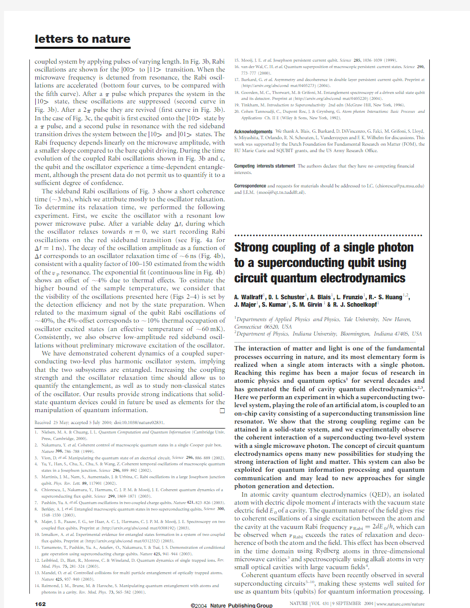
z Figure 1Integrated circuit for cavity QED.a ,The superconducting niobium coplanar
waveguide resonator is fabricated on an oxidized 10£3mm 2silicon chip using optical lithography.The width of the centre conductor is 10m m separated from the lateral ground planes extending to the edges of the chip by a gap of width 5m m resulting in a wave impedance of the structure of Z ?50Q being optimally matched to conventional microwave components.The length of the meandering resonator is l ?24mm.It is coupled by a capacitor at each end of the resonator (see b )to an input and output feed line,fanning out to the edge of the chip and keeping the impedance constant.b ,The capacitive coupling to the input and output lines and hence the coupled quality factor Q is controlled by adjusting the length and separation of the ?nger capacitors formed in the centre conductor.c ,False colour electron micrograph of a Cooper pair box (blue)
fabricated onto the silicon substrate (green)into the gap between the centre conductor (top)and the ground plane (bottom)of a resonator (beige)using electron beam lithography and double angle evaporation of aluminium.The Josephson tunnel junctions are formed at the overlap between the long thin island parallel to the centre conductor and the ?ngers extending from the much larger reservoir coupled to the ground plane.
The transition frequency q r ^g 2/D is now conditioned by the qubit state j z ?^1.Thus,by measuring the transition frequency of the resonator,the qubit state can be determined.Similarly,the level separation in the qubit "eq a t2a ?a g 2=D tg 2=D Tdepends on the number of photons in the resonator.The term 2a ?a g 2/D ,linear in n
?,is the alternating current (a.c.)Stark shift and g 2/D is the Lamb shift.All terms in this hamiltonian,with the exception of the Lamb shift,are clearly identi?ed in the results of our circuit QED experiments.
The properties of this coupled system are determined by probing the resonator spectroscopically 12.The amplitude T and phase f of a microwave probe beam of power P RF transmitted through the resonator are measured versus probe frequency q RF .A simpli?ed schematic of the microwave circuit is shown in Fig.2a.In this set-up,the CPB acts as an effective capacitance that is dependent on its j z eigenstate,the coupling strength g ,and detuning D .This variable capacitance changes the resonator frequency and its transmission spectrum.The transmission T 2and phase f of the resonator for a
far-detuned qubit eg 2=k D ,
,1T;that is,when the qubit is effectively decoupled from the resonator,are shown in Fig.2b and c.In this case,the transmission is a lorentzian of width d n r ?n r /Q ?k /2p at n r ,and the phase f displays a corresponding step of p .The expected transmission at smaller detuning corresponding to a frequency shift ^g 2/D ?k are shown by dashed lines in Fig.2b and c.Such small shifts in the resonator frequency are sensitively measured as a phase shift f ?^tan 21(2g 2/k D )of the transmitted microwave at a ?xed
probe frequency q RF using beam powers P RF which controllably populate the resonator with average photon numbers from n <103down to the sub-photon level n ,,1:We note that both the resonator and qubit can be controlled and measured using capaci-tive and inductive coupling only,that is,without attaching any d.c.connections to either system.
Measurements of the phase f versus n g are shown in Fig.3b,and two different cases can be identi?ed for a Cooper pair box with Josephson energy E J,max /h .n r .In the ?rst case,for bias ?uxes such that E J (F b )/h .n r ,the qubit does not come into resonance with the resonator for any value of gate charge n g (see Fig.3a).As a result,the measured phase shift f is maximum for the smallest detuning D at n g ?1and gets smaller as D increases (see Fig.3b).Moreover,f is periodic in n g with a period of 2e ,as expected.In the second case,for values of F b resulting in E J (F b )/h ,n r ,the qubit goes through resonance with the resonator at two values of n g .Thus,the phase shift f is largest as the qubit approaches resonance (D !0)at the points indicated by red arrows (see Fig.3a,b).As the qubit goes through resonance,the phase shift f changes sign when D changes sign.This behaviour is in perfect agreement with predictions based on the analysis of the circuit QED hamiltonian in the dispersive regime.
In Fig.3c the qubit level separation n a ?E a /h is plotted versus the bias parameters n g and F b .The qubit is in resonance with the resonator at the points [n g ,F b ],indicated by the red curve in one quadrant of the plot.The measured phase shift f is plotted
versus
Figure 2Measurement scheme,resonator and Cooper pair box.a ,The resonator with effective inductance L and capacitance C coupled through the capacitor C g to the Cooper pair box with junction capacitance C J and Josephson energy E J forms the circuit QED system which is coupled through C in/out to the input/output ports.The value of E J is controllable by the magnetic ?ux F .The input microwave at frequency q RF is added to the gate voltage V g using a bias-tee.After the transmitted signal at q RF is ampli?ed using a cryogenic high electron mobility (HEMT)ampli?er and mixed with the local oscillator at q LO ,its amplitude and phase are determined.The circulator and the attenuator prevent leakage of thermal radiation into the resonator.The temperature of individual components is indicated.b ,Measured transmission power spectrum of the resonator (blue dots),the full linewidth dn r at half-maximum and the centre frequency n r are indicated.The solid red line is a ?t to a lorentzian with Q ?n r /dn r <104.c ,Measured transmission phase f (blue dots)with ?t (red line).In panels b and c the dashed lines are theory curves shifted by
^dn r with respect to the data.d ,Energy level diagram of a Cooper pair box.The
electrostatic energy E C (n i 2n g )2,with charging energy E C ?e 2/2C S ,is indicated for n i ?0(solid black line),22(dotted line)and t2(dashed line)excess electrons forming Cooper pairs on the island.C S is the total capacitance of the island given by the sum of the capacitances C J of the two tunnel junctions,the coupling capacitance C g to the centre conductor of the resonator and any stray capacitances.In the absence of Josephson tunnelling the states with n i and n i t2electrons on the island are degenerate at n g ?1.The Josephson coupling mediated by the weak link formed by the tunnel junctions between the superconducting island and the reservoir lifts this degeneracy and opens up a gap proportional to the Josephson energy E J ?E J,max cos(p F b ),where E J,max ?h D Al /8e 2R J ,with the superconducting gap of aluminium D Al and the tunnel junction resistance R J .A ground-state band j #l and an excited-state band j "l are formed with a gate charge and ?ux-bias-dependent energy level separation of E a .
both n g and F b in Fig.3d.We observe the expected periodicity in ?ux bias F b with one ?ux quantum F 0.The set of parameters [n g ,F b ]for which the resonance condition is met is marked by a sudden sign change in f ,which allows a determination of the Josephson energy E J,max ?8.0(^0.1)GHz and the charging energy E C ?5.2(^0.1)GHz.
These data clearly demonstrate that the properties of the qubit can be determined in a transmission measurement of the resonator and that full in situ control over the qubit parameters is achieved.We note that in the dispersive regime this new read-out scheme for the Cooper pair box is most sensitive at charge degeneracy (n g ?1),where the qubit is to ?rst order decoupled from 1/f ?uctuations in its charge environment,which minimizes dephasing 6.This property is advantageous for quantum control of the qubit at n g ?1,a point where traditional electrometry,using a single electron transistor (SET)for example 27,is unable to distinguish the qubit states.We note that this dispersive QND measurement of the qubit state 12is the complement of the atomic microwave cavity QED measurement in which the state of the cavity is inferred non-destructively from the phase shift in the state of a beam of atoms sent through the cavity 3,28.Making use of the full control over the qubit hamiltonian,we then tune the ?ux bias F b so that the qubit is at n g ?1and in resonance with the resonator.Initially,the resonator and the qubit are cooled into their combined ground state j 0,#l ;see inset in
Fig.4b.Owing to the coupling,the ?rst excited states become a doublet j ^l .Similarly to ref.4,we probe the energy splitting of this doublet spectroscopically using a weak probe beam so that n ,,1:The intra-resonator photon number,n ,is calibrated by measuring the a.c.-Stark shift of the qubit in the dispersive case.The resonator transmission T 2is ?rst measured for large detuning D with a probe beam populating the resonator with a maximum of n <1at resonance;see Fig.4a.From the lorentzian line the photon decay rate of the resonator is determined as k /2p ?0.8MHz.The probe beam power is subsequently reduced by 5dB and the transmission spectrum T 2is measured in resonance (D ?0);see Fig.4b.We clearly observe two well-resolved spectral lines separated by the vacuum Rabi frequency n Rabi <11.6MHz.The individual lines have a width determined by the average of the photon decay rate k and the qubit decoherence rate g .The data are in excellent agree-ment with the transmission spectrum numerically calculated using the given value k /2p ?0.8MHz and the single adjustable parameter g /2p ?0.7MHz.
The transmission spectrum shown in Fig.4b is highly sensitive to the photon number in the cavity.The measured transmission spectrum is consistent with the expected thermal photon number of n &0:06(T ,100mK);see red curve in Fig.4b.Owing to the anharmonicity of the coupled atom-cavity system in the resonant case,an increased thermal photon number would reduce
trans-Figure 3Strong coupling circuit QED in the dispersive regime.a ,Calculated level separation n a ?q a /2p ?E a /h between ground j #l and excited state j "l of qubit for two values of ?ux bias F b ?0.8(orange line)and F b ?0.35(green line).The resonator frequency n r ?q r /2p is shown by a blue line.Resonance occurs at n a ?n r symmetrically around degeneracy n g ?^1;also see red arrows.The detuning D /2p ?d ?n a 2n r is indicated.b ,Measured phase shift f of the transmitted microwave for values of F b in a .Green curve is offset by 225deg for visibility.
c ,Calculate
d qubit level separation n a versus bias parameters n g and F b .Th
e resonator frequency n r is indicated by the blue plane.At the intersection,also indicated by the red curve in the lower right-hand quadrant,resonance between the qubit and the resonator occurs (d ?0).For qubit states below the resonator plane the detuning is d ,0,above d .0.d ,Density plot o
f measured phase shift f versus n
g and F b .Light colours indicate positive f (d .0),dark colours negative f (d ,0).The red line is a ?t of the data to the resonance condition n a ?n r .In c and d ,the line cuts presented in a and b are indicated by the orange and the green line,respectively.The microwave probe power P RF used to acquire the data is adjusted suc
h that the maximum intra-resonator photon number n at n r is about ten for g 2=k D ,,1:The calibration of the photon number has been performed in situ by measuring the a.c.-Stark shift of the qubit levels.
mission and give rise to additional peaks in the spectrum owing to transitions between higher excited doublets 30.The transmission spectrum calculated for a thermal photon number of n ?0.5(see green curve in Fig.4b)is clearly incompatible with our experimental data,indicating that the coupled system has in fact cooled to near its ground state,and that we measure the coupling of a single qubit to a single photon.The nonlinearity of the cavity QED system is also observed at higher probe beam powers,as transitions are driven between states higher up the dressed state ladders (not shown).We also observe the anti-crossing between the single photon resonator state and the ?rst excited qubit state by tuning the qubit into and out of resonance with a gate charge near n g ?1and measuring the transmission spectrum (see Fig.4c).The vacuum Rabi peaks evolve from a state with equal weight in the photon and qubit at n g ?1(as shown in Fig.4b)to predominantly photon
states for n g .
.1or n g ,,1:The observed peak positions agree well with calculations considering the qubit with level separation n a ,a single photon in the resonator with frequency n r and a coupling strength of g /2p ;see solid lines in Fig.4c.For a different value of ?ux bias F b such that E a /h ,n r at n g ?1,two anti-crossings are observed (see Fig.4d)again in agreement with theory.
The observation of the vacuum Rabi mode splitting and the corresponding avoided crossings demonstrates that the strong coupling limit of cavity QED has been achieved,and that coherent superpositions of a single qubit and a single photon can be generated on a superconducting chip.This opens up many new possibilities for quantum optical experiments with circuits.Possible applications include using the cavity as a quantum bus to couple widely separated qubits in a quantum computer,or as a quantum memory to store quantum information,or even as a generator and detector of single microwave photons for quantum communication.A
Received 11June;accepted 12July 2004;doi:10.1038/nature02851.
1.Walls,D.&Milburn,G.Quantum Optics (Springer,Berlin,1994).
2.Mabuchi,H.&Doherty,A.Cavity quantum electrodynamics:Coherence in context.Science 298,1372–1377(2002).
3.Raimond,J.,Brune,M.&Haroche,S.Manipulating quantum entanglement with atoms and photons in a cavity.Rev.Mod.Phys.73,565–582(2001).
4.Thompson,R.J.,Rempe,G.&Kimble,H.J.Observation of normal-mode splitting for an atom in an
optical cavity.Phys.Rev.Lett.68,1132–1135(1992).
5.Nakamura,Y.,Pashkin,Y.A.&Tsai,J.S.Coherent control of macroscopic quantum states in a single-Cooper-pair box.Nature 398,786–788(1999).
6.Vion,D.et al.Manipulating the quantum state of an electrical circuit.Science 296,886–889(2002).
7.Martinis,J.M.,Nam,S.,Aumentado,J.&Urbina,C.Rabi oscillations in a large Josephson-junction
qubit.Phys.Rev.Lett.89,117901(2002).
8.Chiorescu,I.,Nakmura,Y.,Harmans,C.J.P .M.&Mooij,J.E.Coherent quantum dynamics of a
superconducting ?ux qubit.Science 299,1869–1871(2003).
9.Yamamoto,T.,Pashkin,Y.A.,Asta?ev,O.,Nakamura,Y.&Tsai,J.S.Demonstration of conditional
gate operation using superconducting charge qubits.Nature 425,941–944(2003).
10.Berkley,A.J.et al.Entangled macroscopic quantum states in two superconducting qubits.Science 300,
1548–1550(2003).
11.Bouchiat,V.,Vion,D.,Joyez,P.,Esteve,D.&Devoret,M.H.Quantum coherence with a single Cooper
pair.Phys.Scr.T76,165–170(1998).
12.Blais,A.,Huang,R.-S.,Wallraff,A.,Girvin,S.&Schoelkopf,R.Cavity quantum electrodynamics for
superconducting electrical circuits:an architecture for quantum computation.Phys.Rev.A 69,062320(2004).
13.Makhlin,Y.,Scho
¨n,G.&Shnirman,A.Quantum-state engineering with Josephson-junction devices.Rev.Mod.Phys.73,357–400(2001).
14.Buisson,O.&Hekking,F.in Macroscopic Quantum Coherence and Quantum Computing (eds Averin,
D.V.,Ruggiero,B.&Silvestrini,P .)(Kluwer,New York,2001).
15.Marquardt,F.&Bruder,C.Superposition of two mesoscopically distinct quantum states:Coupling a
Cooper-pair box to a large superconducting island.Phys.Rev.B 63,054514(2001).
16.Al-Saidi,W.A.&Stroud,D.Eigenstates of a small Josephson junction coupled to a resonant cavity.
Phys.Rev.B 65,014512(2001).
17.Plastina,F.&Falci,https://www.wendangku.net/doc/3f13655767.html,municating Josephson qubits.Phys.Rev.B 67,224514(2003).
18.Blais,A.,Maassen van den Brink,A.&Zagoskin,A.Tunable coupling of superconducting qubits.
Phys.Rev.Lett.90,127901(2003).
19.Yang,C.-P .,Chu,S.-I.&Han,S.Possible realization of entanglement,logical gates,and quantum-information transfer with superconducting-quantum-interference-device qubits in cavity QED.Phys.Rev.A 67,042311(2003).
20.You,J.Q.&Nori,F.Quantum information processing with superconducting qubits in a microwave
?eld.Phys.Rev.B 68,064509(2003).
21.Kiraz,A.et al.Cavity-quantum electrodynamics using a single InAs quantum dot in a microdisk
structure.Appl.Phys.Lett.78,3932–3934(2001).
22.Childress,L.,S?rensen,A.S.&Lukin,M.D.Mesoscopic cavity quantum electrodynamics with
quantum dots.Phys.Rev.A 69,042302(2004).
23.Irish,E.K.&Schwab,K.Quantum measurement of a coupled nanomechanical resonator–Cooper-pair box system.Phys.Rev.B 68,155311(2003).
24.Weisbuch,C.,Nishioka,M.,Ishikawa,A.&Arakawa,Y.Observation of the coupled exciton-photon
mode splitting in a semiconductor quantum microcavity.Phys.Rev.Lett.69,3314–3317(1992).25.Vuckovic,J.,Fattal,D.,Santori,C.,Solomon,G.S.&Yamamoto,Y.Enhanced single-photon emission
from a quantum dot in a micropost microcavity.Appl.Phys.Lett.82,3596(2003).
26.Day,P .K.,LeDuc,H.G.,Mazin,B.A.,Vayonakis,A.&Zmuidzinas,J.A broadband superconducting
detector suitable for use in large arrays.Nature 425,817–821(2003).
27.Lehnert,K.et al.Measurement of the excited-state lifetime of a microelectronic circuit.Phys.Rev.Lett.
90,027002
(2003).
Figure 4Vacuum Rabi mode splitting.a ,Measured transmission T 2(blue line)versus microwave probe frequency n RF for large detuning eg 2=D k ,,1Tand ?t to lorentzian (dashed red line).The peak transmission amplitude is normalized to unity.The inset shows the dispersive dressed states level diagram.b ,Measured transmission spectrum for the resonant case D ?0at n g ?1(blue line)showing the vacuum Rabi mode splitting compared to numerically calculated transmission spectra (red and green lines)for thermal photon numbers of n ?0.06and 0.5,respectively.The dashed red line is the calculated transmission for g ?0and k /2p ?0.8MHz.The inset shows the resonant dressed
states level diagram.c ,Resonator transmission amplitude T plotted versus probe
frequency n RF and gate charge n g for D ?0at n g ?1.Blue colour corresponds to small T ,red colour to large T .Dashed lines are uncoupled qubit level separation n a and resonator resonance frequency n r .Solid lines are level separations found from exact diagonalization of H JC .Spectrum shown in b corresponds to line cut along red arrows.d ,As in c ,but for E J /h ,n r .The dominant character of the corresponding eigenstates is indicated.
28.Nogues,G.et al.Seeing a single photon without destroying it.Nature400,239–242(1999).
29.Schuster,D.I.et al.AC-Stark shift and dephasing of a superconducting quibit strongly coupled to a
cavity?eld.Preprint at https://www.wendangku.net/doc/3f13655767.html,/cond-mat/0408367(2004).
30.Rau,I.,Johansson,G.&Shnirman,A.Cavity QED in superconducting circuits:susceptibility at
elevated temperatures.Preprint at https://www.wendangku.net/doc/3f13655767.html,/cond-mat/0403257(2004). Acknowledgements We thank J.T eufel,B.Turek and J.Wyatt for their contributions to the project and are grateful to P.Day,D.DeMille,M.Devoret,S.Weinreb and J.Zmuidzinas for numerous conversations.This work was supported in part by the National Security Agency and Advanced Research and Development Activity under the Army Research Of?ce,the NSF,the David and Lucile Packard Foundation,the W.M.Keck Foundation,and the Natural Science and Engineering Research Council of Canada.
Competing interests statement The authors declare that they have no competing?nancial interests.
Correspondence and requests for materials should be addressed to A.W.
(andreas.wallraff@https://www.wendangku.net/doc/3f13655767.html,). .............................................................. Generation of ultraviolet entangled photons in a semiconductor
Keiichi Edamatsu1,2,Goro Oohata1,3,Ryosuke Shimizu2&Tadashi Itoh4,2 1Research Institute of Electrical Communication,Tohoku University,Sendai 980-8577,Japan
2CREST,Japan Science and Technology Agency(JST),Japan
3ERATO Semiconductor Spintronics Project,JST,Japan
4Graduate School of Engineering Science,Osaka University,Toyonaka560-8531, Japan ............................................................................................................................................................................. Entanglement is one of the key features of quantum information and communications technology.The method that has been used most frequently to generate highly entangled pairs of photons1,2 is parametric down-conversion.Short-wavelength entangled photons are desirable for generating further entanglement between three or four photons,but it is dif?cult to use parametric down-conversion to generate suitably energetic entangled pho-ton pairs.One method that is expected to be applicable for the generation of such photons3is resonant hyper-parametric scattering(RHPS):a pair of entangled photons is generated in a semiconductor via an electronically resonant third-order non-linear optical process.Semiconductor-based sources of entangled photons would also be advantageous for practical quantum technologies,but attempts to generate entangled photons in semiconductors have not yet been successful4,5.Here we report experimental evidence for the generation of ultraviolet entangled photon pairs by means of biexciton resonant RHPS in a single crystal of the semiconductor CuCl.We anticipate that our results will open the way to the generation of entangled photons by current injection,analogous to current-driven single photon sources6,7.
The material we used in this study was copper chloride(CuCl) single crystal.Because CuCl has a large bandgap(,3.4eV),it is suitable for generating photon pairs in the short wavelength region near ultraviolet.Furthermore,the material has large binding ener-gies for the exciton(,200meV)and biexciton(,30meV).These characteristics have made CuCl one of the most thoroughly inves-tigated materials on the physics of excitons and biexcitons(ref.8 and references therein).In particular,the‘giant oscillator strength’in the two-photon excitation of the biexciton results in a large increase in RHPS ef?ciency,which is advantageous for our experi-ment.In fact the RHPS in CuCl has been observed since the1970s (refs8,9and ref.10and references therein).Figure1a schematically shows the RHPS process in resonance to the biexciton state.The two pump(parent)photons(frequency q i)resonantly create the biexciton,and are converted into the two scattered(daughter) photons(q s,q s0).The biexciton state(G1)created in this process has zero angular momentum(J?0),so we expected the polariza-tions of the daughter photons to be entangled so that their total angular momentum is also zero.With this expectation in mind,we note that polarization correlation between two classical pump beams has been known since the early1980s(ref.11).In practice, instead of the oversimpli?ed picture in Fig.1a,we must consider the exciton-polariton picture;the RHPS obeys the phase-matching condition that takes into account the polariton dispersion relation8. The RHPS in this case is also called two-photon resonant polariton scattering or spontaneous hyper-Raman scattering.In this process, shown in Fig.1b,the biexciton is created from a pair of parent photons(polaritons,more accurately).The sum of the parent photons’energies matches the biexciton energy.The biexciton progressively coherently decays into two polaritons,the sum of whose photon energies,as well as the sum of momenta,is conserved as that of the biexciton.Although the RHPS in CuCl has been known for decades,the possibility of generating entangled photons by this process was theoretically pointed out only lately12.In addition,a large parametric gain via the biexcitonic resonance in CuCl was reported recently13.Similar stimulated parametric scatter-ing of polaritons has also been observed in semiconductor micro-cavities,even at high temperatures14.
In the present experiment,we used a vapour-phase-grown thin single crystal of CuCl.Figure2presents the schematic drawing of our experimental set-up and Fig.3shows the spectrum of light emitted from the sample.The large peak at the downward arrow in Fig.3is the Rayleigh scattered light of the pump beam that was tuned to the two-photon excitation resonance of the biexciton.The two peaks indicated by LEP and HEP(lower and higher energy polaritons)on either side of the pump beam originate from the RHPS.The RHPS is very ef?cient(a few orders of magnitude higher than that of typical parametric down-conversion):We got of the order of1010photons s21sr21by using pump light of,2mW.A pair of photons,one from LEP and the other from HEP,is emitted into different directions according to the phase-matching con-dition,so we placed two optical?bres at appropriate positions and led each photon within the pair into two independent mono-chromators followed by two photomultipliers(PMTs).A time-interval analyser recorded the time interval(t)between the
detected
Figure1Schematic diagram of the resonant hyper-parametric scattering(RHPS)via biexciton.a,Two pump(parent)photons of frequency q i are converted to the two scattered(daughter)photons(q s,q s0).b,The polariton dispersion drawn in two dimensions of momentum space.The biexciton decays into two polaritons that satisfy the phase-matching condition so that both energy and momentum are conserved.The red curve on the polariton-dispersion surface indicates the states on which the phase-matching condition can be satis?ed.