BT137-600D,127;中文规格书,Datasheet资料


1.Product profile
1.1General description
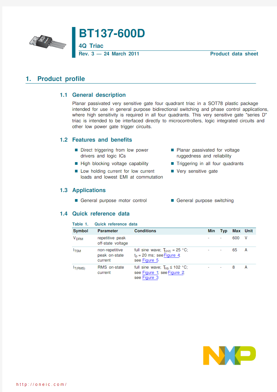
Planar passivated very sensitive gate four quadrant triac in a SOT78 plastic package intended for use in general purpose bidirectional switching and phase control applications, where high sensitivity is required in all four quadrants. This very sensitive gate "series D" triac is intended to be interfaced directly to microcontrollers, logic integrated circuits and other low power gate trigger circuits.
1.2Features and benefits
Direct triggering from low power drivers and logic ICs High blocking voltage capability Low holding current for low current loads and lowest EMI at commutation
Planar passivated for voltage ruggedness and reliability Triggering in all four quadrants Very sensitive gate
1.3Applications
General purpose motor control
General purpose switching
1.4Quick reference data
BT137-600D
4Q Triac
Rev. 3 — 24 March 2011
Product data sheet
Table 1.Quick reference data Symbol Parameter Conditions
Min Typ Max Unit V DRM repetitive peak off-state voltage --600V I TSM
non-repetitive peak on-state current full sine wave; T j(init)=25°C; t p =20ms; see Figure 4;see Figure 5
--65
A
I T(RMS)
RMS on-state current
full sine wave; T mb ≤102°C; see Figure 1; see Figure 2;see Figure 3--8A
2.Pinning information
3.Ordering information
Static characteristics
I GT
gate trigger current
V D =12V;I T =0.1A; T2+ G+; T j =25°C; see Figure 7- 2.55mA V D =12V;I T =0.1A; T2+ G-; T j =25°C; see Figure 7- 3.55mA V D =12V;I T =0.1A; T2- G-; T j =25°C; see Figure 7- 3.55mA V D =12V;I T =0.1A; T2- G+; T j =25°C; see Figure 7
- 6.510mA I H
holding current
V D =12V;T j =25°C;see Figure 9
- 1.5
10
mA
Table 1.Quick reference data …continued Symbol Parameter Conditions
Min Typ Max Unit Table 2.Pinning information Pin Symbol Description Simplified outline Graphic symbol
1T1main terminal 1SOT78 (TO-220AB)
2T2main terminal 23G gate
mb
T2
mounting base;main terminal 2
12mb
3
sym051
T1G
T2
Table 3.
Ordering information
Type number
Package Name
Description
Version BT137-600D
TO-220AB
plastic single-ended package; heatsink mounted; 1 mounting hole; 3-lead TO-220AB
SOT78
4.Limiting values
Table 4.Limiting values
In accordance with the Absolute Maximum Rating System (IEC 60134).
Symbol Parameter
Conditions
Min Max Unit V DRM repetitive peak off-state voltage -600V I T(RMS)RMS on-state current full sine wave; T mb ≤102°C;
see Figure 1; see Figure 2; see Figure 3-8A I TSM
non-repetitive peak on-state current
full sine wave; T j(init)=25°C;
t p =20ms; see Figure 4; see Figure 5-65A full sine wave; T j(init)=25°C; t p =16.7ms
-71A I 2t I 2t for fusing t p =10ms; sine-wave pulse
-21A 2s dI T /dt
rate of rise of on-state current
I T =12A; I G =0.2A; dI G /dt =0.2A/μs; T2+ G+
-50A/μs I T =12A; I G =0.2A; dI G /dt =0.2A/μs; T2+ G--50A/μs I T =12A; I G =0.2A; dI G /dt =0.2A/μs; T2- G--50A/μs I T =12A; I G =0.2A; dI G /dt =0.2A/μs; T2- G+
-10A/μs I GM peak gate current -2A V GM peak gate voltage -5V P GM peak gate power -5W P G(AV)average gate power over any 20 ms period
-0.5W T stg storage temperature -40150°C T j
junction temperature
-125
°C
5.Thermal characteristics
Table 5.Thermal characteristics
Symbol Parameter
Conditions
Min Typ Max Unit R th(j-mb)thermal resistance from junction to mounting base half cycle; see Figure 6-- 2.4K/W full cycle; see Figure 6--2K/W R th(j-a)
thermal resistance from junction to ambient
in free air
-
60
-
K/W
6.Characteristics
Table 6.Characteristics
Symbol Parameter Conditions Min Typ Max Unit Static characteristics
I GT gate trigger current V D=12V;I T=0.1A; T2+ G+;
T j=25°C;see Figure 7
- 2.55mA
V D=12V;I T=0.1A; T2+ G-;
T j=25°C;see Figure 7
- 3.55mA
V D=12V;I T=0.1A; T2- G-;
T j=25°C;see Figure 7
- 3.55mA
V D=12V;I T=0.1A; T2- G+;
T j=25°C;see Figure 7
- 6.510mA
I L latching current V D=12V;I G=0.1A; T2+ G+;
T j=25°C;see Figure 8
- 1.615mA
V D=12V;I G=0.1A; T2+ G-;
T j=25°C;see Figure 8
-8.520mA
V D=12V;I G=0.1A; T2- G-;
T j=25°C;see Figure 8
- 1.215mA
V D=12V;I G=0.1A; T2- G+;
T j=25°C;see Figure 8
- 2.520mA I H holding current V D=12V;T j=25°C;see Figure 9- 1.510mA V T on-state voltage I T=10A; T j=25°C; see Figure 10- 1.3 1.65V
V GT gate trigger voltage V D=12V;I T=0.1A; T j=25°C;
see Figure 11
-0.7 1.5V
V D=400V; I T=0.1A; T j=125°C;
see Figure 11
0.250.4-V
I D off-state current V D=600V; T j=125°C-0.10.5mA Dynamic characteristics
dV D/dt rate of rise of off-state
voltage V DM=402V;T j=125°C;R GT1=1k?;
exponential waveform; gate open circuit
-5-V/μs
t gt gate-controlled turn-on
time I TM=12A; V D=600V; I G=0.1mA;
dI G/dt=5A/μs
-2-μs
7.Package outline
Fig 12.Package outline SOT78 (TO-220AB)
8.Revision history
Table 7.Revision history
Document ID Release date Data sheet status Change notice Supersedes
BT137-600D v.320110324Product data sheet-BT137-600D_2 Modifications:?Various changes to content.
?The format of this data sheet has been redesigned to comply with the new identity guidelines of NXP Semiconductors.
?Legal texts have been adapted to the new company name where appropriate.
BT137-600D_220010601Product specification-BT137_SERIES_D_1
分销商库存信息: NXP
BT137-600D,127
