多核处理器互连网络片上拓扑结构的比较研究(IJCNIS-V9-N11-6)

I. J. Computer Network and Information Security, 2017, 11, 52-62
Published Online November 2017 in MECS (https://www.wendangku.net/doc/576344363.html,/)
DOI: 10.5815/ijcnis.2017.11.06
Interconnect Network on Chip Topology in Multi-core Processors: A Comparative Study
Manju Khari
Department of Electronics and Communication Engineering, AIACTR, Delhi, India
E-mail: manjukhari@yahoo.co.in
Raghvendra Kumar
Department of Computer Science and Engineering, LNCT College, Jabalpur, MP, India
E-mail: raghvendraagrawal7@https://www.wendangku.net/doc/576344363.html,
Dac-Nhuong Le*
Faculty of Information Technology, Haiphong University, Haiphong, Vietnam
E-mail: nhuongld@https://www.wendangku.net/doc/576344363.html,.vn
Jyotir Moy Chatterjee
Department of Computer Science and Engineering, GD-RCET, Bhilai, CG, India
E-mail: jyotirm4@https://www.wendangku.net/doc/576344363.html,
Received: 17 June 2017; Accepted: 01 August 2017; Published: 08 November 2017
Abstract—A variety of technologies in recent years have been developed in designing on-chip networks with the multicore system. In this endeavor, network interfaces mainly differ in the way a network physically connects to a multicore system along with the data path. Semantic substances of communication for a multicore system are transmitted as data packets. Thus, whenever a communication is made from a network, it is first segmented into sub-packets and then into fixed-length bits for flow control digits. To measure required space, energy & latency overheads for the implementation of various interconnection topologies we will be using multi2sim simulator tool that will act as research bed to experiment various tradeoffs between performance and power, and between performance and area requires analysis for further possible optimizations.
Index Terms—Topology, Multicore Processor, Multi2sim Simulator, Super Scalar, Pipeline.
I.I NTRODUCTION
The topology of a network on chip determines how the cores are interconnected. We shall have to ponder over all possible paths where data can be traversed across the network. The routing algorithm selects the specific path a message will take from source to destination. Therein flow control protocols predict the actual path of data towards the designated route, including when & where should the data leaves a core. The micro architecture element recognizes the routing and flow control protocols and carefully maneuvers its circuit’s implementation. Expanding trend of multiple cores is a matter of grave concern, particularly on the die. Subtle & precise understanding is still lacking in the literature of the designing area of the interconnection framework. We know a very little about how it interacts with the rest of the multi-core architecture. A topology would be asserting the number of hops data must route as well as the interconnect lengths between hops. This would be influencing network latency significantly. As routing the data and links consumes energy, the effect of topology on hop count also directly affects network energy consumption.
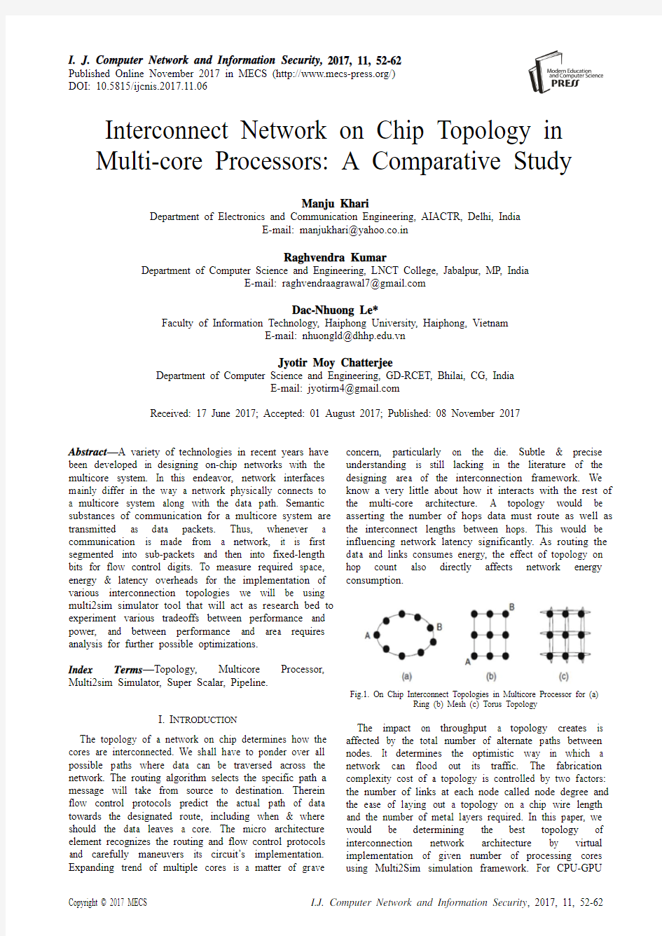
Fig.1. On Chip Interconnect Topologies in Multicore Processor for (a)
Ring (b) Mesh (c) Torus Topology
The impact on throughput a topology creates is affected by the total number of alternate paths between nodes. It determines the optimistic way in which a network can flood out its traffic. The fabrication complexity cost of a topology is controlled by two factors: the number of links at each node called node degree and the ease of laying out a topology on a chip wire length and the number of metal layers required. In this paper, we would be determining the best topology of interconnection network architecture by virtual implementation of given number of processing cores using Multi2Sim simulation framework. For
CPU-GPU
heterogeneous computing, this framework is written in C language and includes templates for superscalar, multithreaded, and multicore CPUs, as well as GPU designs. Thus, the framework would act as perfect model and integration of the main microprocessor components, intended to cover incapability of existing simulators.
II.R ELATED W ORKS
The term Core presupposes a processor unit that can scan instructions & accomplish specific tasks. Syntactic rules are arranged in a manner so as to execute them in real time & formulate into a computer we sense today. Samples from routine life of work require a processing core to open a folder, type into a word document, drawing the desktop environment etc. Gaming on graphics card contains cents of processing cores to promptly work on data in parallel along with some of the computer's processing core. Thus, requirements of designing of cores are extremely complex and cognitive which fluctuate between brands and even models.
In 1965 Gordon Moore stated that the number of transistors on a chip wills approximately double each year (he later refined this, in 1975, to every two years). What is often quoted as Moore's Law is Dave Hour’s revision that computer performance wills double every 18 months. In the early 1970s, Intel manufactured 4-bit 4004 which was first ever microprocessor. It was simply a digit crunching machine. Shortly afterwards they made evolution & produced 8008 and 8080 chips, both 8-bit. Then after Motorola supplanted with its 6800-chip comparative to Intel's 8080. The competitive organizations further fabricated 16-bit microprocessors towards advancement. Motorola served as basis for introduction Intel's 8086 32-bit and later their popular Pentium lineup which were in the first consumer-based PCs [1].
All the generations of processors were constantly designed smaller in area with faster performance requirements it started dissipating more heat and exhausted with more power consumption. Starting from the development of Intel's 8086 through the Pentium 4, there was gradual increase in performance from one generation to another due to the increase in processor frequency. As in case of Pentium 4 the frequency ranged from 1.3 to 3.8 GHz in its 8 years of evolution. On the other hand, physical size of chips decreased while the number of transistors per chip increased. As the clock speeds also increases it aids the heating across the chip by raising temperature to a dangerous level. Speeding processor’s frequency had inspired many in industry throughout a decade’s time however chip designers were still in need for a better technology so as to improve the performance. Due to increasing demand, the idea of having additional processing cores to the same chip came into the mind of designers. Hypothetically it was expected that the performance will double and heat dissipation would be less.
In 2000, SPEC CINT2000 benchmark suite was rolled out which consisted over 5.9 trillion instructions when executed with reference inputs. Researchers substantially rely on simulators to analyze, debug and validate new designs before implementation. Modern hardware like a 3.06GHz Pentium 4 [5] consumes about 31 minutes to conclude the benchmark task. If we were to compare the same hardware with one of the fastest and detailed single-processor, the superscalar models can only simulate about million instructions per second. This would be taking over 72 days to finish one invocation of the SPEC CINT2000 suite. When additional features are infused such as cache-coherent memories and configuration information to boot the Linux kernel, simulation time becomes even more tedious. A fully configured system with cache-coherent simulator will run only 300,000 instructions per second which would be translating it to 228 days for the SPEC CINT2000 suite.
It can be clearly understood by the slow down situation, there is a constant necessity for finding accurate ways and race up the simulation tasks. When power trend reached a barrier in year 2000 for microprocessors, it motivated the research & development of many university scientists aiming to explore scalable designs such as the MIT Raw microprocessor, the Stanford Smart Memories project, the Stanford Merrimac-Streaming Supercomputer, the MIT Scale project, the UW Wave Scalar, the UT Austin TRIPS, the UC Davis Synchro scalar etc. Power consumption and wire delays have limited the continued scaling of centralized systems while making multi core architectures increasingly popular.
In 2007, A research on Migration from Electronics to Photonics in Multicore Processor by an engineer from National University of Singapore suggested that the resistive tendency of metals causes the bottleneck problem in interconnects. By replacing Aluminum with Copper, one is slightly able to improve the interconnect performance provisionally, however to achieve a complete sustainable solution so that ongoing pace of progress persists, it is fairly acceptable to have an idea of having an optical interconnect to metallic wires. Many-core microprocessors are also likely to push performance per chip from the 10 giga flop to the 10tera flop range.
[15]. Table 1 indicated the comparative studies.
Table 1. Comparative Analysis
III.S IMULATION F RAMEWORK
In past years the use of Simple Scalar simulators became very common [8]. It acted as base designs of some of the Multi2Sim modules too. It also shapes an out-of-order superscalar processor. A number of add-ons have been extended in Simple Scalar to design in a more precise way the certain aspects of superscalar processors keeps demanding. However, it is not always easy that a Simple Scalar model can be made to implement latest parallel micro architectures without doing any modifications in the underlying morphology. Still two Simple Scalar Siddons were developed to adapt multithreading in the SSMT [9] and M-Sim [10] simulators. These tools are suitable to fabricate designs stationed on simultaneous multithreaded processors, with the constraint of implementing a set of workloads progressively. The strategy of fixed resource sharing among threads also proves to be a limitation in the case. An endeavor Turandot simulator [11,12] is further inventive effort which simulates a PowerPC architecture. Along with the aid of simultaneous multithread SMT the project was extended for multicore. This effort is made available by the Power-Timer tool [13] as a practical implementation. Tornado addons for parallel micro architectures are ranked under highly researched topics (e.g., [14]), are not available as open source. Both Simple Scalar and Turandot are application-only tools. This means that the simulators would be straightly running the application and simulates its interaction with an underlying virtual operating system. The tool is not prepared to meet the requirements of architecture-specific privileged instruction set as applications cannot be allowed to implement it. The only merit to offer is isolation of the execution instances so that statistics are not affected by a simulation of a real operating system. Multi2Sim is to be categorized as an application-only simulator here.
A key hallmark of chip simulators is “timing-first approach”. It was initiated by GEMS and replicated in Multi2Sim as an addon feature. This approach where timing module is supposed to discover the state of the processor pipeline, instructions helps in spanning over it in an analytical manner. Next functional module is executed along with the instructions dynamically till it attains the commit stage. Thus, legitimate execution paths are perpetually guaranteed by a formerly developed robust simulator. Multi2Sim can be downloaded as a compressed tar file, and has been tested on 32 bit and 64 bit machine architectures, with Ubuntu (Linux OS). The simulator compilation requires the library libbfd, not preset in some Linux distributions by default. All the executables are required to be compiled statically as dynamic linking is not supported. A command line to compile a program composed by a single source file, executables usually have an approximate minimum size of 4MB, since all libraries are linked with it [17, 25]. The following commands are supposed to do us favor in a command terminal to compile it:
tar xzf multi2sim.tar.gz
cd multi2sim
./configure
make
On simulation bench, booting an application is the operation where an executable file is selectively aligned into different virtual memory regions. In physical system, the operating system is responsible for these operations. In comparison to other simulators (e.g. SimpleScalar), Multi2Sim keeps its orientation away from supporting the simulation of an entire Operating System and is confined for running compiled applications only. Thus, loading process must be proactively organized by the simulator at the time of initialization.
The gcc bundle that dissipates executable files as output are intended to adapt the ELF (Executable and Linkable Format) specification. The format design is earmarked to comply with shared libraries, core dumps and object code. An ELF file is made up of an ELF header, a set of segments and a set of sections. Typically, one or more sections are enclosed in a segment. ELF
sections are identified by a name and contain useful data for program loading or debugging. They are labeled with a set of flags that indicate its type and the way they have to be handled during the program loading[3].
When cited, “libbfd” library equips the analysis of the ELF file. It manifests the required operation to query the executable file sections and access its data. The loader module probes the entire set and derives out their characteristic information like starting address, size, flags, and data. When flags stipulate the loadability of a section, its data is replicated into memory with a respective starting address. Loading stage is further followed by the operation of initializing the process stack. With a tendency of growing towards lower region, stack posse’s dynamically variable length memory. The virtual address of its initial address is ought to be “0x7fffffff”. Local variables & parameters are stored in this program stack & while any application is executed the stack pointer (register $sp) gets managed by the own application code. In contrast, when the program starts, it expects some data in it. This loading operation of ELF into virtual memory and analyzing the simulator configuration, is mainly divided into two phases:
?Functional Simulation: The engine which supports the machine design here is MIPS32. It is developed as an autonomous library and supplies interface to the simulator. This simulator kernel is responsible for incurring the functions to create/destroy software contexts, initiate application loading, enumerate existing contexts, consult their status, execute a new instruction and handle speculative execution.
?Detailed Simulation:In Multi2Sim, “Execution-Driven” simulation is performed by the detailed simulator using former functional engine contained in Libkernel. In each cycle, context state is revised by sequence of calls to the kernel on periodic basis. The latest execution of machine instructions invokes analysis process in detailed simulator about its operational nature and records the function latencies consumed by physical entities.
IV.M ULTI-P ROCESSING &P IPELINING D URING
S IMULATION
The pipeline process is basically classified into five stages. First fetch stage inputs the instructions from cache and dispatches them into an IFQ (Instruction Fetch Queue). Next to decode these instructions, decode/ rename stage inputs these instructions from an IFQ, renames its registers and allocate them a block in the ROB (Reorder Buffer). When the input operands are signaled as available, the decoded instructions are placed into a RQ (Ready Queue). Further in issue stage, instructions from the RQ are processed and transmitted to a respective functional unit. In Ex (Execute Stage) the functional units process the task and store its result back into a record file. Finally, the commit stage retires instructions from the ROB in program order [20-24].
This processing flowchart is comparative to the one designed by the SimpleScalar tool set [8]. In additional this uses a ROB, an IQ (Instruction Queue) and a physical record file in place of integrated RUU (Register Update Unit). The sharing strategy of each stage can be varied in a multithreaded pipeline [16] with the Ex stage being the only exception. This scheme aids in achieving superior overall throughput by making use of multithreading. It takes advantage of the sharing of functional units, located in the Ex stage. Thus, utilization is subsequently increased for increasing performance [17-19].
Fig.2 depicts two of the pipeline flow model classified on the basis of stages. Fig.2(a) Stages are shared here among various threads, whereas in Fig.2(b) Except “Ex” stages are looped as many times as endured by hardware threads. The application of Multi2Sim aids in accounting variable stage sharing strategies. The multithread design can be classified as fine-grain (FGMT), coarse-grain (CGMT) or simultaneous multithread (SMT), depending on the stages sharing and thread selection protocols.
Fig.2. Chain of Instruction’s Processing in Pipelining
V.E XPERIMENT ON S IMULATOR &R ESULTS Factors like performance, power/area budget, bandwidth, technology, system software etc. gets affected while inventing out for the best possible design of chip in multiprocessing environments. Latest researches try to orient towards comprehensive analysis of the implementation issues for a design class of chip multiprocessor interconnection network.
Our work does a comparative study of three interconnect network i.e. ring, mesh and torus. Experiments were performed using simulation to find out the best possible combination of core and network for better performance.
A. Experimental Setup for Ring Topology Interconnect: Experiment was performed for Ring Topology Interconnect where number of cores were varied as 2, 4, 8, and 16. The simulation benchmark has to be configured as follows.
The configuration file for 8 cores are shown here:
CPU configuration
[General]
Cores = 8
Threads = 1
Context Configuration
[ Context 0 ]
Exe = radix.x86
args = -p1 -r128 -n262 -m524
Stdout = context-0.out
[ Context 1 ]
Exe = specrand_base.x86
Args = 55 99
Stdout = context-1.out
[ Context 2 ]
Exe = sort.x86
StdOut = context-2.out
[ Context 3 ]
Exe = lu.x86 args = -p1 -n8 -b2
StdOut = context-3.out
Network Configuration [https://www.wendangku.net/doc/576344363.html,0]
DefaultInputBu_erSize = 1024
DefaultOutputBu_erSize = 1024
DefaultBandwidth = 256
; 6 switches
[https://www.wendangku.net/doc/576344363.html,0.Node.sw0]
Type = Switch
[https://www.wendangku.net/doc/576344363.html,0.Node.sw1]
Type = Switch
[https://www.wendangku.net/doc/576344363.html,0.Node.sw2]
Type = Switch
[https://www.wendangku.net/doc/576344363.html,0.Node.sw3]
Type = Switch
[https://www.wendangku.net/doc/576344363.html,0.Node.sw4]
Type = Switch
[https://www.wendangku.net/doc/576344363.html,0.Node.sw5]
Type = Switch
[https://www.wendangku.net/doc/576344363.html,0.Node.n0]
Type = EndNode
[https://www.wendangku.net/doc/576344363.html,0.Node.n1]
Type = EndNode
[https://www.wendangku.net/doc/576344363.html,0.Node.n6]
Type = EndNode
[https://www.wendangku.net/doc/576344363.html,0.Node.n7]
Type = EndNode
[https://www.wendangku.net/doc/576344363.html,0.Node.n2]
Type = EndNode
[https://www.wendangku.net/doc/576344363.html,0.Node.n3]
Type = EndNode
[https://www.wendangku.net/doc/576344363.html,0.Node.n4]
Type = EndNode
[https://www.wendangku.net/doc/576344363.html,0.Node.n5]
Type = EndNode
[https://www.wendangku.net/doc/576344363.html,0.Node.n8]
Type = EndNode
[https://www.wendangku.net/doc/576344363.html,0.Node.n9]
Type = EndNode
; Making a Ring with 6 switches
[https://www.wendangku.net/doc/576344363.html,0.Link.sw0-sw1]
Source = sw0
Dest = sw1
Type = Bidirectional
[https://www.wendangku.net/doc/576344363.html,0.Link.sw1-sw2]
Source = sw1
Dest = sw2
Type = Bidirectional
[https://www.wendangku.net/doc/576344363.html,0.Link.sw2-sw3]
Source = sw2
Dest = sw3
Type = Bidirectional
[https://www.wendangku.net/doc/576344363.html,0.Link.sw3-sw4]
Source = sw3
Dest = sw4
Type = Bidirectional
[https://www.wendangku.net/doc/576344363.html,0.Link.sw4-sw5]
Source = sw4
Dest = sw5
Type = Bidirectional
[https://www.wendangku.net/doc/576344363.html,0.Link.sw5-sw0]
Source = sw5
Dest = sw0
Type = Bidirectional
; Links from Switches to Main Memory
[https://www.wendangku.net/doc/576344363.html,0.Link.sw0-n2]
Source = sw0
Dest = n2
Type = Bidirectional
[https://www.wendangku.net/doc/576344363.html,0.Link.sw1-n3]
Source = sw1
Dest = n3
Type = Bidirectional
[https://www.wendangku.net/doc/576344363.html,0.Link.sw2-n4]
Source = sw2
Dest = n4
Type = Bidirectional
[https://www.wendangku.net/doc/576344363.html,0.Link.sw3-n5]
Source = sw3
Dest = n5
Type = Bidirectional
[https://www.wendangku.net/doc/576344363.html,0.Link.sw4-n8]
Source = sw4
Dest = n8
Type = Bidirectional
[https://www.wendangku.net/doc/576344363.html,0.Link.sw5-n9]
Source = sw5
Dest = n9
Type = Bidirectional
; Links from Switches to L2 caches
[https://www.wendangku.net/doc/576344363.html,0.Link.sw1-n0]
Source = sw1
Dest = n0
Type = Bidirectional
[https://www.wendangku.net/doc/576344363.html,0.Link.sw2-n1]
Source = sw2
Dest = n1
Type = Bidirectional
[https://www.wendangku.net/doc/576344363.html,0.Link.sw3-n6]
Source = sw3
Dest = n6
Type = Bidirectional
[https://www.wendangku.net/doc/576344363.html,0.Link.sw4-n7]
Source = sw4
Dest = n7
Type = Bidirectional
Simulation results for Ring Topology Interconnect shows that there is significant improvemen t in “Dispatch IPC” with number of cores. It is to be noted here that, initially the “Dispatch IPC” increases but after 4 cores it remains constant. The “Issue IPC” also increases up to 4 cores and after 4 cores it comes to steady state. There is significa nt improvement in “Commit IPC” for Ring Topology with number of cores as 2 and 4. After 4 cores, no significant improvement in commit IPC is seen. The average latency increases for 2 and 4 cores. For 8 and 16
cores, it remains constant. Therefore, it can be concluded the 4 cores is acting as optimal number for Ring Topology Interconnect.
B. Experimental Setup for Mesh Topology Interconnect: Experiments performed for Mesh Topology Interconnect had the variation for number of cores as 2, 4, 8, and 16. The simulation was setup by various configuration files.
The configuration file for 8 cores are shown here:
CPU Configuration
[General]
Cores = 8
Threads = 1
Context Configuration
[ Context 0 ]
Exe = radix.x86
args = -p1 -r128 -n262 -m524
Stdout = context-0.out
[ Context 1 ]
Exe = specrand_base.x86
Args = 55 99
Stdout = context-1.out
[ Context 2 ]
Exe = sort.x86
StdOut = context-2.out
[ Context 3 ]
Exe = lu.x86 args = -p1 -n8 -b2
StdOut = context-3.out
Network Configuration s
[https://www.wendangku.net/doc/576344363.html,0]
DefaultInputBu_erSize = 1024
DefaultOutputBu_erSize = 1024
DefaultBandwidth = 256
; 6 switches
[https://www.wendangku.net/doc/576344363.html,0.Node.sw0]
Type = Switch
[https://www.wendangku.net/doc/576344363.html,0.Node.sw1]
Type = Switch
[https://www.wendangku.net/doc/576344363.html,0.Node.sw2]
Type = Switch
[https://www.wendangku.net/doc/576344363.html,0.Node.sw3]
Type = Switch
[https://www.wendangku.net/doc/576344363.html,0.Node.sw4]
Type = Switch
[https://www.wendangku.net/doc/576344363.html,0.Node.sw5]
Type = Switch
[https://www.wendangku.net/doc/576344363.html,0.Node.n0]
Type = EndNode
[https://www.wendangku.net/doc/576344363.html,0.Node.n1]
Type = EndNode
[https://www.wendangku.net/doc/576344363.html,0.Node.n6]
Type = EndNode
[https://www.wendangku.net/doc/576344363.html,0.Node.n7]
Type = EndNode
[https://www.wendangku.net/doc/576344363.html,0.Node.n2]
Type = EndNode
[https://www.wendangku.net/doc/576344363.html,0.Node.n3]
Type = EndNode
[https://www.wendangku.net/doc/576344363.html,0.Node.n4]
Type = EndNode
[https://www.wendangku.net/doc/576344363.html,0.Node.n5]
Type = EndNode
[https://www.wendangku.net/doc/576344363.html,0.Node.n8]
Type = EndNode
[https://www.wendangku.net/doc/576344363.html,0.Node.n9]
Type = EndNode
; Making a Mesh with 6 switches
[https://www.wendangku.net/doc/576344363.html,0.Link.sw0-sw1]
Source = sw0
Dest = sw1
Type = Bidirectional
[https://www.wendangku.net/doc/576344363.html,0.Link.sw1-sw2]
Source = sw1
Dest = sw2
Type = Bidirectional
[https://www.wendangku.net/doc/576344363.html,0.Link.sw2-sw3]
Source = sw2
Dest = sw3
Type = Bidirectional
[https://www.wendangku.net/doc/576344363.html,0.Link.sw3-sw4]
Source = sw3
Dest = sw4
Type = Bidirectional
[https://www.wendangku.net/doc/576344363.html,0.Link.sw4-sw5]
Source = sw4
Dest = sw5
Type = Bidirectional
[https://www.wendangku.net/doc/576344363.html,0.Link.sw5-sw0]
Source = sw5
Dest = sw0
Type = Bidirectional
[https://www.wendangku.net/doc/576344363.html,0.Link.sw1-sw4]
Source = sw1
Dest = sw4
Type = Bidirectional
; Links from Switches to Main Memory
[https://www.wendangku.net/doc/576344363.html,0.Link.sw0-n2]
Source = sw0
Dest = n2
Type = Bidirectional
[https://www.wendangku.net/doc/576344363.html,0.Link.sw1-n3]
Source = sw1
Dest = n3
Type = Bidirectional
[https://www.wendangku.net/doc/576344363.html,0.Link.sw2-n4]
Source = sw2
Dest = n4
Type = Bidirectional
[https://www.wendangku.net/doc/576344363.html,0.Link.sw3-n5]
Source = sw3
Dest = n5
Type = Bidirectional
[https://www.wendangku.net/doc/576344363.html,0.Link.sw4-n8]
Source = sw4
Dest = n8
Type = Bidirectional
[https://www.wendangku.net/doc/576344363.html,0.Link.sw5-n9]
Source = sw5
Dest = n9
Type = Bidirectional
; Links from Switches to L2 caches
[https://www.wendangku.net/doc/576344363.html,0.Link.sw1-n0]
Source = sw1
Dest = n0
Type = Bidirectional
[https://www.wendangku.net/doc/576344363.html,0.Link.sw2-n1]
Source = sw2
Dest = n1
Type = Bidirectional
[https://www.wendangku.net/doc/576344363.html,0.Link.sw3-n6]
Source = sw3
Dest = n6
Type = Bidirectional
[https://www.wendangku.net/doc/576344363.html,0.Link.sw4-n7]
Source = sw4
Dest = n7
Type = Bidirectional
For this topology too, initially the “Dispatch IPC” was noted to be increased till 4 cores & remains constant afterwards. The “Issue IPC” was showing the same tends as “Dispatch IPC” i.e. increases up to 4 cores and after that there was no remarkable variation. From 2 to 4 cores, the “Commit IPC” showed improvement and after 4 cores no significant improvement was observed on simulation bench. As the number of core is increased from 2 to 4, the average latency increases. After 4 cores i.e. for core 8 and 16, average latency is seen as constant. Therefore, it can be concluded the 4 cores is acting as optimal number for Mesh Topology Interconnect too.
C. Experimental Setup for Torus Topology Interconnect: Experiments performed for Torus Topology Interconnect consisted the variation for number of cores as 2, 4,8, and 16. The simulation was setup by various configuration files.
The configuration file for 8 cores are shown here:
CPU configuration
[General]
Cores = 8
Threads = 1
Context Configuration
[ Context 0 ]
Exe = radix.x86
args = -p1 -r128 -n262 -m524
Stdout = context-0.out
[ Context 1 ]
Exe = specrand_base.x86
Args = 55 99
Stdout = context-1.out
[ Context 2 ]
Exe = sort.x86
StdOut = context-2.out
[ Context 3 ]
Exe = lu.x86
args = -p1 -n8 -b2
StdOut = context-3.out
Network Configurations
[https://www.wendangku.net/doc/576344363.html,0]
DefaultInputBu_erSize = 1024
DefaultOutputBu_erSize = 1024
DefaultBandwidth = 256
; 6 switches
[https://www.wendangku.net/doc/576344363.html,0.Node.sw0]
Type = Switch
[https://www.wendangku.net/doc/576344363.html,0.Node.sw1]
Type = Switch
[https://www.wendangku.net/doc/576344363.html,0.Node.sw2]
Type = Switch
[https://www.wendangku.net/doc/576344363.html,0.Node.sw3]
Type = Switch
[https://www.wendangku.net/doc/576344363.html,0.Node.sw4]
Type = Switch
[https://www.wendangku.net/doc/576344363.html,0.Node.sw5]
Type = Switch
; 2 L2s
[https://www.wendangku.net/doc/576344363.html,0.Node.n0]
Type = EndNode
[https://www.wendangku.net/doc/576344363.html,0.Node.n1]
Type = EndNode
[https://www.wendangku.net/doc/576344363.html,0.Node.n6]
Type = EndNode
[https://www.wendangku.net/doc/576344363.html,0.Node.n7]
Type = EndNode
; 4 Main Memory access points
[https://www.wendangku.net/doc/576344363.html,0.Node.n2]
Type = EndNode
[https://www.wendangku.net/doc/576344363.html,0.Node.n3]
Type = EndNode
[https://www.wendangku.net/doc/576344363.html,0.Node.n4]
Type = EndNode
[https://www.wendangku.net/doc/576344363.html,0.Node.n5]
Type = EndNode
[https://www.wendangku.net/doc/576344363.html,0.Node.n8]
Type = EndNode
[https://www.wendangku.net/doc/576344363.html,0.Node.n9]
Type = EndNode
; Making a Torus with 6 switches
[https://www.wendangku.net/doc/576344363.html,0.Link.sw0-sw1]
Source = sw0
Dest = sw1
Type = Bidirectional
[https://www.wendangku.net/doc/576344363.html,0.Link.sw1-sw2]
Source = sw1
Dest = sw2
Type = Bidirectional
[https://www.wendangku.net/doc/576344363.html,0.Link.sw2-sw3]
Source = sw2
Dest = sw3
Type = Bidirectional
[https://www.wendangku.net/doc/576344363.html,0.Link.sw3-sw4]
Source = sw3
Dest = sw4
Type = Bidirectional
[https://www.wendangku.net/doc/576344363.html,0.Link.sw4-sw5]
Source = sw4
Dest = sw5
Type = Bidirectional
[https://www.wendangku.net/doc/576344363.html,0.Link.sw5-sw0]
Source = sw5
Dest = sw0
Type = Bidirectional
[https://www.wendangku.net/doc/576344363.html,0.Link.sw0-sw2]
Source = sw0
Dest = sw2
Type = Bidirectional
[https://www.wendangku.net/doc/576344363.html,0.Link.sw0-sw3]
Source = sw0
Dest = sw3
Type = Bidirectional
[https://www.wendangku.net/doc/576344363.html,0.Link.sw0-sw4]
Source = sw0
Dest = sw4
Type = Bidirectional
[https://www.wendangku.net/doc/576344363.html,0.Link.sw1-sw3]
Source = sw1
Dest = sw3
Type = Bidirectional
[https://www.wendangku.net/doc/576344363.html,0.Link.sw1-sw4]
Source = sw1
Dest = sw4
Type = Bidirectional
[https://www.wendangku.net/doc/576344363.html,0.Link.sw1-sw5]
Source = sw1
Dest = sw5
Type = Bidirectional
[https://www.wendangku.net/doc/576344363.html,0.Link.sw2-sw4]
Source = sw2
Dest = sw4
Type = Bidirectional
[https://www.wendangku.net/doc/576344363.html,0.Link.sw2-sw5]
Source = sw2
Dest = sw5
Type = Bidirectional
[https://www.wendangku.net/doc/576344363.html,0.Link.sw3-sw5]
Source = sw3
Dest = sw5
Type = Bidirectional
;Links from Switches to Main Memory
[https://www.wendangku.net/doc/576344363.html,0.Link.sw0-n2]
Source = sw0
Dest = n2
Type = Bidirectional
[https://www.wendangku.net/doc/576344363.html,0.Link.sw1-n3]
Source = sw1
Dest = n3
Type = Bidirectional
[https://www.wendangku.net/doc/576344363.html,0.Link.sw2-n4]
Source = sw2
Dest = n4
Type = Bidirectional
[https://www.wendangku.net/doc/576344363.html,0.Link.sw3-n5]
Source = sw3
Dest = n5
Type = Bidirectional
[https://www.wendangku.net/doc/576344363.html,0.Link.sw4-n8]
Source = sw4
Dest = n8
Type = Bidirectional
[https://www.wendangku.net/doc/576344363.html,0.Link.sw5-n9]
Source = sw5
Dest = n9
Type = Bidirectional
; Links from Switches to L2 caches
[https://www.wendangku.net/doc/576344363.html,0.Link.sw1-n0]
Source = sw1
Dest = n0
Type = Bidirectional
[https://www.wendangku.net/doc/576344363.html,0.Link.sw2-n1]
Source = sw2
Dest = n1
Type = Bidirectional
[https://www.wendangku.net/doc/576344363.html,0.Link.sw3-n6]
Source = sw3
Dest = n6
Type = Bidirectional
[https://www.wendangku.net/doc/576344363.html,0.Link.sw4-n7]
Source = sw4
Dest = n7
Type = Bidirectional
The simulation results for Torus Topology Interconnect again showed that there is no significant improvement in “Dispatch IPC” after 4 cores. Initially the “Dispatch IPC” increases till 4 cores & remains same afterwards. As we increase cores from 2 to 4, the “Issue IPC” increases proportionally. After 4 cores, it remains almost constant. The “Commit IPC” was seen to be rapidly changing from 2 to 4 cores. After that i.e. for 8 and 16 cores, no significant improvement in “Commit IPC” was seen. The average latency increases for 2 and 4 cores. After that i.e. for 8 and 16 cores it too remains constant. Hence it can be concluded that number of cores which is giving best result for Torus Topology Interconnect is 4 cores. The combined performance of the three topologies for interconnect network at their best suitable core i.e. 4 cores for various parameters like “Dispatch IPC”, “Issue IPC”, “Commit IPC” and “Average Latency”.
Fig.3. Simulation Result’s Comparison
Fig.4. Torus Topology Simulation Result
VI.C ONCLUSIONS
On simulation environment, various scenarios of multicore processing were observed & optimal number of cores requirement was found to be 4. Hence, combined performance for various parameters like dispatch IPC, issue IPC, commit IPC and average latency of Ring, Mesh & Torus interconnect network topologies for 4 cores was observed & compared. Since this work is devoted to find the best interconnect network topology, the average latency is considered to compare the networks. The average latency is observed to be minimum for Torus Topology and also all IPCs are observed to be minimum. It is to be concluded that the Torus with 4 cores is the best suitable interconnect network topology for designing. The “timing-first” scheme supported by Multi2Sim framework helps in taking account of efficiency & robustness in as customized manner. It also provides opportunity of experimenting simulations on a variety of deep levels. The uniqueness in this context is the execution
of
“timing-first” simulation along wit h functional units. Hence there is no requirement to simulate a whole operating system. Executing parallel workloads with dynamic threads creation would be sufficient. The simulation framework which we have used has been developed for adapting the key attributes of popular simulators like partitioning functional and timing simulation, SMT and multiprocessor support and cache coherence. The module of the simulator also supports application of execution-driven simulation like SimpleScalar. This design facilitates the unitization of the functional kernel as an independent library plus allows the definition of the instruction set to be mapped into a central file (machine.def).
R EFERENCES
[1]Schauer, B. (2008). Multicore processors - a
necessity. ProQuest discovery guides, 1-14.
[2]Mukherjee, S. S., Bannon, P., Lang, S., Spink, A., &
Webb, D. (2002). The Alpha 21364 network architecture. IEEE micro, 22(1), 26-35.
[3]Ubal, R., Sahuquillo, J., Petit, S., & Lopez, P. (2007,
October). Multi2Sim: A Simulation Framework to Evaluate Multicore-Multithreaded Processors. In Sbac-
Pad (pp.62-68).
[4]Owens, J. D., Dally, W. J., Ho, R., Jayasimha, D. N.,
Keckler, S. W., &Peh, L. S. (2007). Research challenges for on-chip interconnection networks. IEEE micro, 27(5), 96-108.
[5]Barr, K. C. (2006). Summarizing multiprocessor program
execution with versatile, microarchitecture-independent snapshots (Doctoral dissertation, Massachusetts Institute of Technology).
[6]Nanehkaran, Y. A., & Ahmadi, S. B. B. (2013). The
Challenges of Multi-Core Processor. International Journal of Advancements in Research & Technology, 2(6), 36-39.
[7]McLean, R. A. R. A. (1984). Applied factorial and
fractional designs (No. 04; QA279, M2.).
[8]Burger, D., & Austin, T. M. (1997). The SimpleScalar
tool set, version 2.0. ACM SIGARCH computer architecture news, 25(3), 13-25.
[9]Madoń, D., Sanchez, E., &Monnier, S. (1999, August). A
study of a simultaneous multithreaded processor implementation. In European Conference on Parallel Processing (pp. 716-726). Springer, Berlin, Heidelberg. [10]Sharkey, J., Ponomarev, D., &Ghose, K. (2005). M-sim: a
flexible, multithreaded architectural simulation environment. Techenical report, Department of Computer Science, State University of New York at Binghamton. [11]Moudgill, M., Bose, P., & Moreno, J. H. (1999, February).
Validation of Turandot, a fast processor model for microarchitecture exploration. In Performance, Computing and Communications Conference, 1999 IEEE International (pp. 451-457). IEEE.
[12]Moudgill, M., Wellman, J. D., & Moreno, J. H. (1999).
Environment for PowerPC microarchitecture exploration. IEEE Micro, 19(3), 15-25.
[13] D. Brooks, P. Bose, V. Srinivasan, M. Gschwind, and M.
Rosenfield P. Emma. Microarchitecutre-Level Power-
Performance Analysis: The Power Timer Approach. IBM J. Research and Development, 47(5/6), 2003.
[14]Lee, B., & Brooks, D. (2005). Effects of pipeline
complexity on SMT/CMP power-performance efficiency. Power, 106, 1. [15]Xu, Z. (2008). Migration from electronics to photonics in
multicore processor(Doctoral dissertation, Massachusetts Institute of Technology).
[16]Shen, J. P., &Lipasti, M. H. (2013). Modern processor
design: fundamentals of superscalar processors.
Waveland Press.
[17]Umbarkar, A. J., Rothe, N. M., &Sathe, A. S. (2015).
OpenMP teaching-learning based optimization algorithm over multi-core system. International Journal of Intelligent Systems and Applications, 7(7), 57.
[18]Khan, Z. A., Siddiqui, J., &Samad, A. (2015). Linear
crossed cube (LCQ): A new interconnection network topology for massively parallel system. International Journal of Computer Network and Information Security, 7(3), 18.
[19]Dehghani, F., &Darooei, S. (2016). A Novel Architecture
for Adaptive Traffic Control in Network on Chip using Code Division Multiple Access Technique. International Journal of Computer Network and Information Security, 8(8), 20.
[20]
Nazir, L., & Mir, R. N. (2016). Realization of Efficient High Throughput Buffering Policies for Network on Chip Router. International Journal of Computer Network and Information Security, 8(7), 61.
[21]Rustogi, S., Sharma, M., &Morwal, S. (2017). Improved
Parallel Apriori Algorithm for Multi-cores. International Journal of Information Technology and Computer Science (IJITCS), 9(4), 18.
[22]Joseph, P. M., Rajan, J., Kuriakose, K. K., & Murty, S. S.
(2013). Exploiting SIMD Instructions in Modern Microprocessors to Optimize the Performance of Stream Ciphers. International Journal of Computer Network and Information Security, 5(6), 56.
[23]Le, D. N. (2013). Optimizing the cMTS to Improve
Quality of Service in Next Generation Networks based on ACO Algorithm. International Journal of Computer Network and Information Security, 5(4), 25.
[24]Basmadjian, R., & de Meer, H. (2012, May). Evaluating
and modeling power consumption of multi-core processors. In Proceedings of the 3rd International Conference on Future Energy Systems: Where Energy, Computing and Communication Meet (p. 12). ACM. [25]M2S Guide 4.2, The Multi2Sim Simulation Framework,
https://www.wendangku.net/doc/576344363.html,.
Authors’ Profiles
Prof. Manju Khari is Assistant Professor at
the Ambedkar Institute of Advanced
Communication Technology and Research,
under Govt. Of NCT Delhi , affiliated with
Guru Gobind Singh Indraprastha University),
India. She is also Professor In-charge of the
IT Services of the Institute and has more
than twelve years' experience in Network Planning & Management. She holds a Ph.D. in Computer Science & Engineering from the National Institute of Technology Patna and received her Master's degree in Information Security from Ambedkar Institute technology of Advanced Communication Technology and Research, Delhi, India. Her research interests are in software testing, software quality, software metrics, information security and nature-inspired algorithms. She has published 60 papers in refereed national and International journals and conferences, and has authored 6 book chapters and co-authored two books. She is a
life member of various International and national research societies (SDIWC, IAENG, etc.) She is also Guest Editor of the International Journal of Advanced Intelligence Paradigms, reviewer for the International Journal of Forensic Engineering, and Editorial Board Member of the International Journal of Software Engineering and Knowledge Engineering.
Raghvendra Kumar, Ph.D, is working as Assistant Professor in Computer Science and Engineering Department at L.N.C.T Group of College Jabalpur, M.P. India. He received B. Tech. in Computer Science and Engineering from SRM University Chennai
(Tamil Nadu), India, M. Tech. in Computer Science and Engineering from KIIT University, Bhubaneswar, (Odisha) India and Ph.D. in Computer Science and Engineering from Jodhpur National University, Jodhpur (Rajasthan), India. He has published 86 research papers in international / National journal and conferences including IEEE, Springer and ACM as well as serve as session chair, Co-chair, Technical program Committee members in many international and national conferences and serve as guest editors in many special issues from reputed journals (Indexed By: Scopus, ESCI). He also received best paper award in IEEE Conference 2013 and Young Achiever Award-2016 by IEAE Association for his research work in the field of distributed database. His researches areas are Computer Networks, Data Mining, cloud computing and Secure Multiparty Computations, Theory of Computer Science and Design of Algorithms. He authored 12 computer science books in field of Data Mining, Robotics, Graph Theory, and Turing Machine by IGI Global Publication, USA, IOS Press Netherland, Lambert Publication, Scholar Press, Kataria Publication, Narosa, Edupedia Publication, S. Chand Publication and Laxmi Publication.
Dac-Nhuong Le has a M.Sc. and Ph.D in computer science from Vietnam National University, Vietnam in 2009 and 2015, respectively. He is Deputy-Head of Faculty of Information Technology, Haiphong University, Vietnam. Presently, he is also the Vice-Director of Information Technology Apply and Foreign Language Training Center
in the same university . He has a total academic teaching experience of 12 years with many publications in reputed international conferences, journals and online book chapter contributions (Indexed By: SCI, SCIE, SSCI, Scopus, ACM, DBLP). His area of research includes: evaluation computing and approximate algorithms, network communication, security and vulnerability, network performance analysis and simulation, cloud computing, IoT and image processing in biomedical. His core work in network security, soft computing and IoT and image processing in biomedical. Recently, he has been the technique program committee, the technique reviews, the track chair for international conferences: FICTA 2014, CSI 2014, IC4SD 2015, ICICT 2015, INDIA 2015, IC3T 2015, INDIA 2016, FICTA 2016, ICDECT 2016, IUKM 2016, INDIA 2017, CISC 2017 under Springer-ASIC/LNAI Series. Presently, he is serving in the editorial board of international journals and he authored 4 computer science books by Springer, IGI Global, Lambert Publication, Scholar Press.
Jyotir Moy Chatterjee is working as Assistant Professor in Department of Computer Science and Engineering at GD-RCET, Bhilai, C.G, India. He received M. Tech from KIIT University, Bhubaneswar, Odisha and B. Tech in Computer Science & Engineering from Dr. MGR Educational &
Research Institute University, Chennai, (Tamil Nadu). He is the member of CSI. His research interests include the cloud computing, big data, privacy preservation and data mining. He is also Oracle Certified OCA 10g and IBM Certified Associate System Administrator Lotus Notes and Domino 8.
How to cite this paper: Manju Khari, Raghvendra Kumar, Dac-Nhuong Le, Jyotir Moy Chatterjee,"Interconnect Network on Chip Topology in Multi-core Processors: A Comparative Study", International Journal of Computer
Network and Information Security(IJCNIS), Vol.9, No.11, pp.52-62, 2017.DOI: 10.5815/ijcnis.2017.11.06