水下井口系统(vetco公司)

Subsea wellhead systems Advanced solutions for extreme conditions
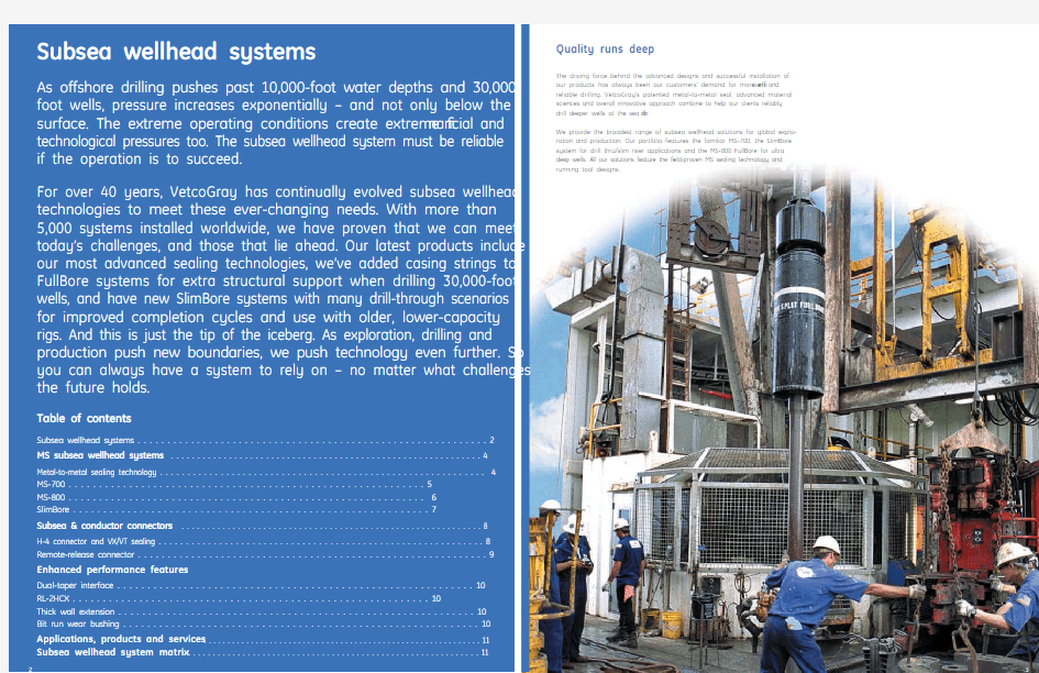
The driving force behind the advanced designs and successful installation of our products has always been our customers’ demand for more ef? cient and reliable drilling. VetcoGray’s patented metal-to-metal seal, advanced material sciences and overall innovative approach combine to help our clients reliably drill deeper wells at the sea ? oor.
We provide the broadest range of subsea wellhead solutions for global explo-ration and production. Our portfolio features the familiar MS-700, the SlimBore system for drill thru/slim riser applications and the MS-800 FullBore for ultra deep wells. All our solutions feature the ? eld-proven MS sealing technology and
running tool designs.
MS-700
Developed in 1991, the MS-700 is the most widely used subsea wellhead system in the world. Its versatility has been proven across TLP/Spar tieback, subsea completion and deepwater drilling applications.
Features and bene? ts
Metal-to-metal sealing
Fundamental to the MS-700 subsea wellhead system is the MS seal which has been proven to be the most reliable metal-to-metal seal offered in the industry.
Dual tapered sockets
The tapered socket design between the high-pressure and low-pressure housing reduces fatigue in the casing by transmitting the load directly into the conductor housing. No preloading is required to get maximum bending capacity. Below-mudline equipment
16” submudline equipment allows an additional casing string to be hung at a predetermined position under the wellhead. The system is installed with a single trip running tool that installs both the casing hanger and the seal..Running tools
Since the inception of the MS-700, VetcoGray has provided a host of running
tools that reduce operating times and risk associated with drilling a subsea well.
MS-700 subsea wellhead system
MS subsea wellhead systems
MS-700
VetcoGray provides a host of running tools that have proven their
reliability in over 5,000 subsea wellhead installations.
Metal-to-metal sealing technology
MS sealing
All VetcoGray’s subsea wellheads bene? t from our metal-to-metal sealing
technology – superior to elastomer options because it prevents inevitable heat and corrosive ? uids from damaging seal integrity. Both the wellhead and hanger have a sealing area of parallel
wickers. Once the seal is properly installed these wickers act as both the seal-ing and locking mechanism. The seal is installed with a combination of weight and pressure typically applied with the PADPRT, pushing the energizing ring between the metal “U” seal and expanding it into the wicker pro? les. This “U” seal expansion forces the wickers into the softer seal metal creating a reliable seal even if the wickers have been damaged.Emergency sealing
VetcoGray has several contingencies for sealing. The ? rst is the MS-E which is installed via the running tool in the same manner as the MS-1. The only difference between the MS-E and the MS-1 is the soft binary alloy. The binary alloy allows for softer material to ? ow into damaged areas. Another option is the SG-TPR. The SG-TPR includes an elastomer and metal
sealing combination that seals below the wicker area.
SlimBore
As many older rigs are being brought back into service to meet increasing demand, operators are facing new challenges when drilling in deep water. Weight restrictions require smaller risers/BOPs/less mud. Trips to run trees and tubing hanger spools cost more today than ever due to unprecedented day rates.
Key features and bene? ts
Trip saving
VetcoGray’s SlimBore wellhead system enables operators to cut trip time in half when using a subsea completion system. In Drill-Thru (DT) mode, a hori-zontal tree can be run immediately after running the subsea wellhead system. From that point, all drilling and completion operations can be performed. The SlimBore system can provide savings potential in a non-DT mode as well, simply by using a smaller riser, less drilling mud and a smaller BOP stack – enabling the use of an older generation rig which generates signi? cant day rate savings.MS-1 sealing
The SlimBore system uses reliable MS-1 sealing technology. This seal is rated to 10,000 psi and has 500,000 lbs lockdown rating.Running Tools
The SlimBore system utilizes most of the same tools as the MS-700 system.
MS-800 FullBore
Developed in 2007 and based on proven technology, the MS-800 takes the industry standard to the next level – providing a cost-effective system that can be utilized in all applications including shallow water and deep wells. FullBore enables the operator to run one extra casing string under BOP control with a 21” drilling riser. The system also allows more ? exibility in designing casing programs by using larger drill bits, testing packoffs to higher pressures and having the option to run 18” and 16” casing strings below the mudline. Furthermore, the system allows potentially larger completion options, by reaching total depth with a larger production string.
Key features and bene? ts
Running tools
The MS-800 18” and 16” casing hanger running tools set and test the seal via the drill pipe. This reduces valuable rig time.Below-mudline equipment
The MS-800 FullBore system features the industry’s highest rated below-mudline equipment. The 16” casing hanger equipment is rated at 2.00 MM lbs casing weight capacity at 10,000 psi – and includes VetcoGray’s true metal-to-metal sealing.
Casing hanger load ring actuation
The load-bearing jewellery is located on the casing hanger and is actuated by a tag shoulder. Once the casing hanger is set, the running tool will actuate the MS seal and test in a single trip.20 KSI capabilities
MS-800 is also available for high-pressure (20,000 psi) and high-temperature (350°F) applications.
SlimBore subsea wellhead system
MS-800 FullBore subsea wellhead system
MS-700PADPRT casing hanger RT 90ft SlimBore wellhead joints installed from a barge offshore Brazil
MS-800
MS-800 casing hanger load ring detail
SMAC pin Visual indicator
View port
Piston
Latch ring
SMAC box
Remote-release connector
Subsea wellhead retrieval is made easy with VetcoGray’s ROV-operated Sub-mudline Abandonment Connector (SMAC), welded to the 30” or 36” conductor. Once the well has been abandoned, the casing is cut and the SMAC is disengaged for retrieval back to the rig. This wellhead equipment can usually be refurbished for use in other subsea wells.
H-4 connector and VX/VT sealing
All VetcoGray subsea wellheads come with the proven reliability of our H-4 con-nector – used on more than 50% of the ? oater rigs drilling today. The stainless steel VX2/VT2 gasket, located between the connector and wellhead, is rated for 15,000 psi and 250°F. The latest in our line of connectors is the DW HD H-4 connector. This connector is a high-capacity wellhead connector that provides 5.25 million ft lbs of bending load capacity when coupled with the DMS subsea
wellhead.
H-4 Connector
The industry standard for offshore drilling and production
Conductor connectors
Subsea connectors
SMAC connector
VetcoGray has been an industry-leading supplier of products, systems and services for drilling, completion and production for more than a century. Our specialty wellheads, trees, valves, connectors, controls and related systems provide superior performance around the globe - onshore, offshore and sub-sea. We design products for the unique challenges of extreme pressure and temperature applications, at both ends of the spectrum. As part of GE’s Oil & Gas business, we regularly incorporate new technologies and resources devel-oped throughout the extensive GE network, with each advancement helping our customers achieve greater levels of performance and productivity.
Applications
? Capital drilling systems
? Floating drilling systems
? Onshore drilling systems
? Offshore surface systems
? Subsea drilling systems
? Subsea processing and power Products and Services
? BOP connectors
? Casing connectors
? Diverters
? Flow assurance systems
? Gate Valves
? Installation tooling and service ? Intelligent well technology ? Manifolds and templates
? Marine risers
? Mudline suspension
? Subsea control systems
? Subsea electrical connections ? Subsea ? owline connections ? Subsea manifolds
? Subsea separation
? Subsea tree systems
? Subsea wellheads
? Surface wellheads
? Surface tree systems
Subsea wellhead system matrix Enhanced performance; reduced time/cost
Extending equipment life
Dual-taper interface
Extreme bending moments seen in subsea drilling and SPAR/TLP applications have led VetcoGray to develop the dual-tapered socket feature. This inter-face is placed between the upper and lower pro? le of the high pressure and conductor housing. Introduced in 1991, the tapered socket design has proven itself to be the best in class for dispersing the effects of high currents, drive off or fatigue-related loads.
RL-2HCX
In addition to the wellhead tapered socket interface, VetcoGray offers an added solution for fatigue and high bending. The RL-2HCX conductor connec-tor is a pre-loaded, high strength connector with a 2 start thread for make up in less than one turn.
Thick wall extension
SPAR/TLP applications can create high fatigue loading on the 22”/20” exten-sion from the high pressure housing. Addition of a thick wall extension reduces stress concentrations by creating a smoother transition from the wellhead housing to the casing. Trip saving features
Bit run wear bushing
VetcoGray offers a variety of solutions designed to decrease the amount of
time required to drill a well. Our wear bushing or nominal seat protector can
be run into the wellhead and left for retrieval at a later time or can be retrieved
on each bit trip. The drill-ahead tool is another time-saving device that allows
the next casing string to be drilled after jetting in the conductor, effectively
eliminating one trip.
Drill ahead tool
Bit run nominal seat protector
S trength and stability
1011
G E Oil & Gas
Headquarters
Nuovo Pignone S.p.A.
Via Felice Matteucci 2
50127 Florence Italy
T +39 055 423 211
F +39 055 423 2800
customer.service.center@https://www.wendangku.net/doc/6f5272950.html,
VetcoGray Inc.
Headquarters
3010 Briarpark Avenue, Suite 300 Houston, Texas 77042
P.O. Box 2291
Houston, Texas 77252-2291
T +1 713 683 2400
F +1 713 683 2421
For complete contact information, please refer to our https://www.wendangku.net/doc/6f5272950.html,/vetcogray
The information contained herein is general in nature
and is not intended for speci? c construction, installation
or application purposes. GE reserves the right to make
changes in speci? cations or add improvements at any
time without notice or obligation.
?2008 General Electric Company
All Rights Reserved
GEOG_VG_subsea_wellhead_011108_V2
GE imagination at work
GB T 21412.4 《水下井口装置和采油树设备》目录(等同于ISO 13628.4-1999)
GB/T21412《石油天然气工业水下生产系统的设计与操作》分为九个部分: ---第1部分:总要求和建议; ---第2部分:水下和海上用软管系统; ---第3部分:过出油管(TFL)系统; ---第4部分:水下井口装置和采油树设备; ---第5部分:水下控制管缆; ---第6部分:水下生产控制系统; ---第7部分:修井和(或)完井立管系统; ---第8部分:水下生产系统远程作业机器人(ROV)接口; ---第9部分:远程作业工具(ROT)维修系统。 本部分为GB/T21412的第4部分,对应于ISO136284:1999《石油和天然气工业水下生产系统的设计与操作第4部分:水下井口装置和采油树设备》(英文第1版)。本部分等同翻译ISO136284:1999,为了便于使用,本部分做了下列编辑性修改: ---ISO13628的本部分改为GB/T21412的本部分或本部分; ---用小数点.代替作为小数点的逗号,; ---将ISO136284:1999中的ISO10423和ISO10423:1994统一为ISO10423:1994; ---在第2章引用文件中,用ISO13533、ISO13625、ISO13628 3 分别代替APISpec16A、APISpec16R、APIRP17C 并增加了标准中文名称; ---对表面粗糙度值进行了转换; ---表7(A)中转换了螺栓直径并增加了螺栓孔直径公制尺寸值;表9(B)和表10(B)中增加了螺栓孔直径公制尺寸值; ---表G.1中增加了螺栓直径和螺距公制尺寸值; ---删除了ISO136284:1999的前言和引言; ---增加了本部分的前言。 本部分的附录E、附录G 和附录H 为规范性附录,附录A、附录B、附录C、附录D、附录F和附录I为资料性附录。 本部分由全国石油钻采设备和工具标准化技术委员会(SAC/TC96)提出并归口。 本部分负责起草单位:宝鸡石油机械有限责任公司。 本部分参加起草单位:中国海洋石油总公司、石油工业井控装置质量监督检验中心。 本部分主要起草人:杨玉刚、范亚民、李清平、张斌。 目录 前言Ⅴ 1 范围1 2 规范性引用文件3 3 术语、定义、符号和缩略语3 3.1 术语和定义3 3.2 符号和缩略语8 4 使用条件和产品规范级别9 4.1 使用条件9 4.2 产品规范级别PSL 9 5 系统一般要求10
水下采油树模型开发技术方案
水下采油树模型开发技术方案 一、主要技术规范 a 执行标准:API SPEC 6A19 b 额定工作压力:70Mpa(10000psi) c 公称通径:主通径:Φ65mm(2 9/16in) 旁通径:Φ65mm(2 9/16in) d 额定温度级别:P.U(-29℃~121℃) e 材料级别:DD f 产品规范等级:PSL3 g 性能要求级别:PR1 h 总体尺寸(长×宽×高):3130mm×560 mm×2540 mm 主要技术要求:系统工作压力HP:7500psi,LP:5000psi;电源耐压5kv;HP输入1路、输出2路、回油1路;LP输入1路、输出16路、回油1路。 外形尺寸:1400mm*900mm*1400mm 环境温度:操作温度0℃~+40℃ 储藏温度-18℃~+50℃ 工作压力:LP 5000psi, HP 7500psi 主要功能:接收SCM发出信号,开启、关闭阀门,通断油路,检测SC M按照主控站指令发出控制命令功能;向SCM提供温度、压力信号并记录,检测SCM对温度、压力信号的接收和传输能力。 采油树是整个生产系统的执行部分,通过控制采油树管线上的阀门,来控制整个采油系统的流程。整个采油树生产执行主要分为三个部分:生产主回路、环空回路、药剂注入回路。 二、采油树主要组成 ?树体(TREE BODY) ?采油树与井口回接系统(CONNECTOR TIE-BACK) ?井口连接器(WELLHEAD CONNECTOR) ?采油树帽(INTERNAL TREE CAP)
?阀门(VALVE BLOCK & VALVE) ?ROV控制盘(ROV CONTROL PANEL) ?化学药剂注入(CHEMICAL INJECTION) ?采油树体总成(X’TREE ASSEMBLY) 2.1 树体(TREE BODY) ?整体加工的空心园筒体 ?内部形状加工成与油管挂和采油树内帽相配合的形状 ?下端及顶部为螺纹状结构,分别与18-3/4″ 10000PSI工作压力的FMC TORUS IV液压井 口连接器及采油树帽相连接 ?为连接PMV(生产主阀), AMV(环状通路主阀)及AAV (环形空间入口阀)开孔 ?Quad Penetrator装置, 该装置通过与油管挂上的液压Penetrator连接装置相接, 可以 控制井下安全阀的状态 2.2 采油树与井口回接系统(CONNECTOR TIE-BACK) 该系统由上下两部分组成,它的主要功能是为采油树体和水下井口之间的18-3/4″VX 型垫片提供第二道屏障,它的上部分叫做Upper Alignment Stab,其顶部与树体相接并密封,其下部分叫Lower Alignment Stab,其底部与9-5/8″的套管悬挂器相接并密封,中间由上下两部分相接并密封,这里所有的密封均采用金属附加弹性体的方式,能承受5000 PSI 的压力。有此回接系统,井口和采油树之间的连接密封就不会受到井下压力的作用,其可靠性大为增强 4.3 井口连接器(WELLHEAD CONNECTOR) ?完井顺序 ?30″井口套管 ?18-3/4″水下井口 ?13-3/8″套管悬挂器 ?9-5/8″套管悬挂器 ◆连接水下井口 ?采油树生产导向基础(PGB)首先座落在30″井口套管(Housing) 上, PGB上的重力锁紧 装置自动与套管锁紧 ?采油树沿PGB导向绳及导向柱(Guidepost)就位 ?FMC TorusIV-18-3/4″10000 PSI(工作压力)的液压采油树连接器与18-3/4″水下井 口连接锁紧
水下井口
DRIL-QUIP公司的SS-10 C型水下井口系统, 该系统是靠钢圈金属面密封的,抗压10000psi。SS-10 C型水下井口系统具有以下特点: ●操作简便、安全、可靠; ●使用较少的送入工具; ●密封总成靠金属密封; ●重力坐封密封总成; ●同一个密封总成适用于所有的13-3/8”套管和较小尺寸的套管; ●密封总成可以直接被起出来而不需要转动; ●下入过程中不能左转; ●所有的套管悬挂器在井口头处自动居中; ●套管悬挂器周围有较大面积的流道; ●套管悬挂器可以被锁定在井口头处; ●可以在下入抗磨补芯的条件下对防喷器试压; ●所有的套管悬挂器上都有标准的水下回接面; ●系统安装步骤简单,使用工具少。 一、准备工作: 运送前仔细检查SS-10水下井口系统的所有部件,保证在不被破坏,在使用前处于良好的状态。 1、检查永久导向基板(PGB)的零件号是否与30”套管头的零件号相匹配,并记录 PGB的零件号和序列号; 2、检查固定销钉、锁紧销钉,确保可以插入导向柱板上的销钉孔内; 3、检查导向柱,确保BOP可以顺利插入导向柱; 4、检查PGB上部中央固定环,看是否有裂纹、滑痕、凹痕等; 5、事先在PGB上安装水平仪,检查是否与PGB垂直,并确定水平仪安装在ROV 可以看到的地方; 6、在30”井口头以下5米涂上白漆,每0.5米涂一道白漆,在30”导管以上5米涂 上白漆,每0.5米一道; 二、30”井口头的下入顺序 1、连接30”井口头送入工具,在工具上部接631*410的变扣接头,上面接一柱加重 钻杆,立于钻台; 2、在月池上装好永久性导向基板和导向柱,为了便于辨认,将导向柱涂上白漆并 按顺序编号;在导向柱上安装上导向绳; 3、一开钻36”井眼至122米(水深40米,转盘面高度25米); 4、下30”浮鞋穿过转盘面到月池,通水检查浮鞋是否正常,继续下套管穿过导向基 板,在套管通过PGB的时候注意观察不要被挂住; 5、在最后一根导管上接30”井口头,然后坐在转盘面上。下5”钻杆做固井内管柱, 接30”导管送入工具,转动送入工具,使送入工具外径上的4个防旋转销钉插入 到对应的井口头槽内,左转送入工具大约5圈,旋转力使锁定环扩大插入到相 应的30”井口头的槽内,此时内管柱离导管鞋约12-15米; 6、下送入工具、30”井口头和导管至月池,在井口头安装在PGB上之前,保证4个 锁紧销钉已经插入到PGB上对应的插孔里,将导管和30”井口头座在PGB里面, 让PGB上部的控制环咬紧30"井口头上部; 7、打开井口头送入工具上的排气阀,将井口头送入水面,接顶驱循环排气。停泵5 分钟再循环一次,在确保导管串内灌满海水后,关闭排气阀;
6水下生产控制系统
水下生产控制系统验证测试 水下生产控制系统应进行质量鉴定试验以验证设备在特定工作条件下的性能。作为替代,制造商应提供与工业实际(设备按指定要求即将完成的)相一致的证明文件或其他客服证据。 这一条款规定了用来鉴定产品设计的质量鉴定试验。用于设计鉴定的设备或工装夹具应该是在设计,尺寸和材料方面具有代表性的生产模型。 如所设计产品的安装,形式,功能或材料上有任何变化,制造厂应文字记录这些变化对产品性能的影响。重大的设计变动就成为一个新的设计需要重新认证(重大变动是指由制造厂确定的影响产品在其作业环境中性能的变化)。如材料的适应性能通过其他方法实现,材料的变化不需要重新认证。 应对SEM进行形型式试验以鉴定温度循环和振动相关的设计。 进行所有试验时应考虑人员安全和对周围区域潜在的破坏。 宜进行综合实验程序以确保满足控制系统的性能要求。 1.质量鉴定试验 1.1净水压力试验(内部和外部) 作为质量鉴定试验的一部分,宜对所有的受压组件或装备进行静水压力试验。额定压力小于或等于103.4MPa(15000 psi)时应在1.5倍的设计压力下进行静水压力试验。额定工作压力超过103.4MPa(15000 psi)时的内部净水压力试验应在1.25倍设计压力下进行。外部静水压力试验应在1.1倍设计围压下进行。 试验压力应在任何组件,管线或节点没有外部流体泄露的情况下最少保持10min。 试验期间所有的液压蓄能器应与回路隔离。 控制设备的低压部分,如适用,包括储液罐,低压过滤器,泵吸入管线和系统返回管线,都不进行静水压力(试验压力)试验。 1.2 最小和最大温度试验 应进行质量鉴定试验以证明小于或等于最小额定工作温度,大于或等于最大额定工作温度时的设备性能。 1.3 周期试验 对具有周期操作性能的设备应进行模拟长期现场作业的质量鉴定试验。试验周期应等于或超过指定应用的周期。 2.出厂验收试验(FA T)
水下井口系统(vetco公司)
Subsea wellhead systems Advanced solutions for extreme conditions
The driving force behind the advanced designs and successful installation of our products has always been our customers’ demand for more ef? cient and reliable drilling. VetcoGray’s patented metal-to-metal seal, advanced material sciences and overall innovative approach combine to help our clients reliably drill deeper wells at the sea ? oor. We provide the broadest range of subsea wellhead solutions for global explo-ration and production. Our portfolio features the familiar MS-700, the SlimBore system for drill thru/slim riser applications and the MS-800 FullBore for ultra deep wells. All our solutions feature the ? eld-proven MS sealing technology and running tool designs.
水下生产系统知识讲解
水下生产系统 第一章:水下生产系统发展概述 1、从浅水走向深水 原因 ?对能源需求的增长 ?陆上及浅水资源开发已经到达成熟期,并开始减少。 ?高油价,降低开发成本 ?深水技术的快速发展(深水钻井技术、水下增压和分离技术等) 水深、环境条件、油气田位置和油气输送成本等综合因素决定了油田的开发方案 为何采用水下生产系统? ?能将井口布置在现有平台有效钻井范围以外的地方; ?高油价,降低开发成本; ?深水技术的快速发展(深水钻井技术、水下增压和分离技术等) 2、水下生产系统组成 立管和海管、水下采油树、水下增压系统、水下分离系统、回注系统、水下管汇、跨接管、管道终端、连接器 3、我国水下生产系统发展展望 1)国外规范和成熟经验是重要参考资料 2)但由于中国南海海域的特殊条件(台风频繁、较强的内波流作用、复杂海底 地形、油田离岸距离远等),相关的技术不可能完全照搬,必须针对南海的独特海况与离岸距离,做出创新性的研究与设计。 3)采油树结构复杂,涉及机械、力学、密封、材料、控制、安全、钻井、海洋 工程等学科。一旦具备了水下采油树的设计、制造、安装和测试能力,就可以设计制造其他水下产品,突破国外技术封锁,自主开发深水油气田。 第二章:立管系统 立管主要功能 ?生产立管:将流体从地底油藏传输到海面浮式设施 ?注入立管:回注气体或液体到地底油藏 ?外输立管:将处理过的油气传输到陆上或穿梭油轮 ?钻井立管:钻井工具通道
立管类型 从本身的特点可分为钢悬链线立管(SCR)、顶部张紧立管(TTR)、柔性立管(FR)、混合立管(HR) 深水立管的主要挑战: ?立管系统的费用对水深非常敏感; ?立管系统的安装费用对水深也非常敏感; ?安装时需要具有足够能力的特殊安装船舶; ?对于焊接和检验质量的要求高; ?在立管设计中的主要考虑因素为重量和疲劳寿命。 立管的组装 ?柔性立管和脐带缆通过陆上组装而成; ?SCR通过立管安装船舶焊接作业线组装而成; ?TTR通过连接法兰或连接接头组装而成。 SCR容易发生破坏的部位 顶部柔性接头和底部触地点 TTR顶部张紧系统形式 浮筒式和张紧器式 FR优点 ?无VIV ?连接和解脱方便 ?疲劳寿命长 ?管线在海底覆盖面积小 ?可重复利用 ?抗腐蚀性能好 FR类型 UN-BONDED PIPE 和BONDED PIPE 混合立管特性 ?经济有效 ?具有独立的浮筒 ?对浮式平台的负载小 ?紧凑构型–占地面积小 ?在有限的空间内能容纳多根立管 ?消除了单独垂直立管的相互影响 ?无管土相互作用影响 立管设计考虑因素
水下采油系统
l水下采油系统介绍 水下采油系统是将全部或部分油气集输装备置于海底的水下生产系统。该系统主要包括:水下采油树、水下底盘、水下管汇、跨接管、海洋立管、脐带缆等设备。水下采油系统的出现,解决了在深水中使用固定式平台而使成本急剧上升的问题;水下采油系统多与浮式生产系统配合工作。在水下系统中,井口头和采油树都在海底;因此,水下生产系统就不会像在水上的生产系统(如刚性平台)那样受到海面风浪流和水深的影响。但另一方面,水下生产系统不能直接进行操作,操控也必须通过脐带缆远程控制,持续地操作显然比平台式生产系统复杂得多。水下生产系统的费用基本上随水深变化而变化,而刚性平台的费用是随着水深的增加而增加的;因此,对于深水区域,多趋向于使用水下生产系统。图l为简单的水下采油系统,该系统的工作原理为:油气从水下井口上的采油树采出,经海底管线送到水下管汇进行计量、收集、初步处理,再通过海洋立管输送,然后被运往岸上做进一步处理。 1.1水下采油树 采油树最初被称为十字树、x型树或者圣诞树。它是位于通向油井顶端开口处的一个组件,它包括用来测量和维修的阀门、安全系统和一系列监视器械。它连接了来自井下的生产管道和出油管;同时,作为油井顶端 ̄uJ,t-部环境隔绝开的重要屏障。采油树还包括:许多可以用来调节或阻止所产原油蒸汽、天然气和液体从井内涌出的阀门;采油树是通过海底管线连接到生产管汇系统的。水下采油树的诞生使低成本地开发深水油气田成为可能。 1.2水下管汇 水下管汇主要用来分配、控制管理石油和天然气的流动。水下管汇安装在海底井群之间,主要是将数口油井的油气集巾起来,再通过一条输油管线混合油流,送到最近的采油平台或岸上基地做进一步处理,它可以减少海底管线的长度(见图3)。管汇终端包括一些大型的结构(如:水下加工系统)都属于水下管汇;因此,水下管汇类型有许多种。 水下管汇和油井在结构上是完全独立的,油井和出油管道通过跨接管与管汇相连。水下管汇由管汇、管汇支撑结构、基础结构和保护盖三部分组成。 1管汇。管汇由管线、阀门、控制模块、流动仪表等组成。管汇中心的管线
丛式井水下生产系统钻井中心布局探讨
57卷增刊1 2016年11月 中国造船 SHIPBUILDING OF CHINA Vol.57 Special 1 Nov. 2016 文章编号:1000-4882 (2016) S1-0031-07 丛式井水下生产系统钻井中心布局探讨 刘飞,李清平,刘伟 (中海油研究总院,北京100027) 摘 要 针对水下油气田开发方式中常见的丛式井布局形式,从丛式井钻井中心布局的设计要素、钻井中心水下 连接系统设计、水下预留接口位置这三个方面,进行了深入分析探讨,给出了丛式丼水下生产系统钻丼中心 布局的总体设计原则及水下连接系统设备选型的思路和方法。 关键词:水下生产系统;钻井中心;丛式井;水下布局;水下连接 中图分类号:TE54 文献标识码:A 0引言 水下生产系统中水下井口的位置通常由钻井工程师根据油藏靶点的位置和最优钻井轨迹来决定。对于钻井来说,直井的钻井成本是最低的,斜度井和水平井会増加钻井长度和钻井难度,进而増加钻 井时间和成本。但是,斜度井和水平井技术可以将若干口井集中在一个钻井中心,钻井船停留在一个 钻井中心,可以通过收放锚链这样简单的操作,实现钻井船位置的移动,完成若干口井的钻井工作,减少了钻井船长距离移动时重复抛锚的工作量。斜度井和水平井技术日趋成熟,钻井成本逐渐降低,若干个水下井口集中布置在一个钻井中心周围,简化了管线和脐带缆的路由和连接,可以节省大量的 工程费用。 水下生产系统主要有三种井口组合方式,即卫星井、丛式井和集中式基盘[1]。卫星井方式为单个 水下井口回接到周边依托设施;丛式井为多个水下井口(通常为3?12 口)分散地布置在中心管汇的周 围,通过跨接管和跨接缆与中心管汇连接,如图1所示。而集中式基盘方式则为若干个水下采油树集 成在管汇结构当中,如图2所示。水下井口具体采用哪种组合形式,需要根据安装船舶资源、操作维 图1丛式井布局图2集中式基盘布局
一般水下井口系统
水下井口系统 水下井口系统(Fig. 1)是一个压力容器,在钻井过程中,它提供了套管的悬挂和密封途径。井口还为水下防喷器和隔水管提供了锁紧端面,使之可以连接到浮式钻机上。用这种方法,到达井口的路径就处于压力可控的环境中了。水下井口系统位于海底,需要使用下入工具和钻杆进行远程安装。 Fig. 1—图例是一种典型的水下井口系统,安装了临时弃井盖帽。井口中配置了额30 × 20 × 13? × 9? × 7-in的套管。
Contents 1 水下井口系统 o 1.1 Drilling guide base o 1.2 Low-pressure housing o 1.3 High-pressure housing o 1.4 Casing hangers o 1.5 Metal-to metal annulus seal assembly o 1.6 Bore protectors and wear bushings o 1.7 Running and test tools 1.7.1 Conductor wellhead running tool 1.7.2 High-pressure wellhead running tool 1.7.3 Casing-hanger seal-assembly running tool 1.7.4 Multipurpose tool and accessories 1.7.5 BOP isolation test tool 1.7.6 Seal-assembly running tool
水下井口系统 水下井口在内径上设计了一个着陆台肩,位于井口本体的底部。后续的套管悬挂器都挂在之前的套管悬挂器上。套管会悬挂在套管悬挂器的顶部,最终全部累加在最初一级的着陆台肩上。每一个套管悬挂器都通过密封,将井口罩内部与悬挂器外部隔开,该密封总成采用真正的金属对金属密封。这种密封总成在套管之间形成了压力隔离。 一旦钻井结束,井口就会提供一个生产管柱和水下采油树的接口,或者,如果有需要的话,一个回接到平台的点。 水下井口系统的设计目的有两点: ◆为作业者提供最新的设备技术,除了功能超强,还能针对井的问题融合最可靠 的解决方案 ◆提供易于安装的系统,节省安装和钻机时间 一个标准的水下井口系统应包括以下内容: 钻井引导基座. 低压罩. 高压井口罩(一般是18? in.). 套管悬挂器(各种尺寸,基于井身设计). 金属对金属的环空密封总成. 井眼保护装置和耐磨补心. 下入工具和测试工具.
水下油气生产系统控制模块组成及应用
水下油气生产系统控制模块组成及应用 摘要本文以南海某气田工程项目为背景,介绍了水下采油树控制模块在油气田开发中的使用情况,简单分析了水下控制模块的工作原理、组成结构以及控制方式,为今后水下油气生产系统中电液复合控制系统的使用提供实践参考。 关键词复合电液控制;水下生产系统;控制系统;水下控制模块 前言 南海某气田位于中国南海东部珠江口盆地,距香港东南约250公里,水深最深约350米。该气田依靠气田自身压力,通过水下采油树利用海底管道接到PY 中心平台,然后接到LW中心平台,与气田群生产的天然气混合后,外输至陆地终端。 1 水下生产控制系统 目前海洋油气开发工程中,水下生产控制系统大致分为三类:全液压控制系统(直接液压、先导液压、顺序液压);电液控制系统(直接电控液压系统、复合电液控制系统、光电复合液压控制系统)和全电式控制系统[1]。该气田控制系统采用了复合电液控制系统,将多个水下控制模块连接到同一根脐带缆的终端上,在平台或浮体上的控制室可以操作水下设备的阀门及获取工作状态。其特点是响应速度快、传输距离长、易实现集中控制。 2 水下控制模块系统 水下控制模块是复合电液控制方式的重要组成部分,水下控制模块(SCM)用于采集水下设施的数据、井下数据,控制水下阀门的开启、闭合。主要完成内部压力传感器、节流阀位置指示器、下游压力/温度传感器、环空压力传感器、井下压力/温度传感器、上游压力/温度传感器、多相流量计、化学药剂注入计量阀、腐蚀监测器及砂传感器等的数据采集,并将信息发送至水面主控站,典型外部连接图见图1。 2.1 水下电子模块(SEM)系统 水下电子模块(SEM)是水下采油树控制模块的核心部件,采用冗余设计。主要功能是接收水面主控站的控制信号,完成电磁阀的换向,从而引导液压液的流向来驱动阀门执行器;另外,采集水下采油设备上的传感器数据,经过处理后传送到水面主控站,实现水下油气生产的检测作用,保证水下生产的顺利进行。 水下电子模块采用模块化设计,包括阀门控制板、通信接口板(包括内部总线通讯及外部通讯卡)、电源板、I/O板(数据采集板)和主控板等。主控站可以对SEM程序进行重新配置,具备大容量的内存,可临时存储相关数据,典型水
水下油气生产系统控制模块组成及应用
龙源期刊网 https://www.wendangku.net/doc/6f5272950.html, 水下油气生产系统控制模块组成及应用 作者:李文祥王琨郭骏 来源:《科学与信息化》2017年第05期 摘要本文以南海某气田工程项目为背景,介绍了水下采油树控制模块在油气田开发中的使用情况,简单分析了水下控制模块的工作原理、组成结构以及控制方式,为今后水下油气生产系统中电液复合控制系统的使用提供实践参考。 关键词复合电液控制;水下生产系统;控制系统;水下控制模块 前言 南海某气田位于中国南海东部珠江口盆地,距香港东南约250公里,水深最深约350米。该气田依靠气田自身压力,通过水下采油树利用海底管道接到PY中心平台,然后接到LW中心平台,与气田群生产的天然气混合后,外输至陆地终端。 1 水下生产控制系统 目前海洋油气开发工程中,水下生产控制系统大致分为三类:全液压控制系统(直接液压、先导液压、顺序液压);电液控制系统(直接电控液压系统、复合电液控制系统、光电复合液压控制系统)和全电式控制系统[1]。该气田控制系统采用了复合电液控制系统,将多个 水下控制模块连接到同一根脐带缆的终端上,在平台或浮体上的控制室可以操作水下设备的阀门及获取工作状态。其特点是响应速度快、传输距离长、易实现集中控制。 2 水下控制模块系统 水下控制模块是复合电液控制方式的重要组成部分,水下控制模块(SCM)用于采集水下设施的数据、井下数据,控制水下阀门的开启、闭合。主要完成内部压力传感器、节流阀位置指示器、下游压力/温度传感器、环空压力传感器、井下压力/温度传感器、上游压力/温度传感器、多相流量计、化学药剂注入计量阀、腐蚀监测器及砂传感器等的数据采集,并将信息发送至水面主控站,典型外部连接图见图1。 2.1 水下电子模块(SEM)系统 水下电子模块(SEM)是水下采油树控制模块的核心部件,采用冗余设计。主要功能是接收水面主控站的控制信号,完成电磁阀的换向,从而引导液压液的流向来驱动阀门执行器;另外,采集水下采油设备上的传感器数据,经过处理后传送到水面主控站,实现水下油气生产的检测作用,保证水下生产的顺利进行。
水下采油树液压控制系统设计与仿真
2018年10月第46卷第20期机床与液压MACHINETOOL&HYDRAULICSOct 2018Vol 46No 20DOI:10.3969/j issn 1001-3881 2018 20 017 收稿日期:2017-04-09 基金项目:中国博士后科学基金资助项目(2016M592269) 作者简介:张长齐(1989 ),男,硕士,助理工程师,研究方向为固完井井下工具设计开发和水下采油树控制系统设计三E-mail:zhangcq@shelfoil com三水下采油树液压控制系统设计与仿真 张长齐1,黄鲁蒙2,李富平1,阮臣良1,张彦廷2 (1 中国石化石油工程技术研究院德州大陆架石油工程技术有限公司,山东德州253005;2 中国石油大学(华东)机电工程学院,山东青岛266580) 摘要:实现对水下采油树的控制是保证水下生产正常进行的必要条件三通过分析API标准要求,结合水下采油树阀门执行器工作参数,设计水下采油树液压控制系统,包括液压动力单元和水下控制模块,并对相关元件进行计算和选型三根据控制系统要求,利用AMESim软件,建立水下采油树液压控制系统模型,对水下采油树阀执行器的开启和关闭过程进行响应分析三结果表明:所设计的液压控制系统可以满足水下采油树控制要求三 关键词:水下采油树;液压控制系统;计算选型 中图分类号:TE952一一文献标志码:A一一文章编号:1001-3881(2018)20-074-6DesignandSimulationonHydraulicControlSystemforSubseaTree ZHANGChangqi1,HUANGLumeng2,LIFuping1,RUANChenliang1,ZHANGYanting2(1 ShelfoilPetroleumEquipment&ServicesCo.,Ltd.,SinopecResearchInstituteofPetroleumEngineering,DezhouShandong253005,China;2 CollegeofMechanicalandElectronicEngineering,ChinaUniversityofPetroleum,QingdaoShandong266580,China)Abstract:Theprecisecontrolforsubseatreeisthekeypointtoensuresubseaproductionrunningnormally.BasedontheresearchforAPIstandardsandoperatingparametersofsubseatreevalveactuator,hydrauliccontrolsystemforsubseatreewasdesigned,includinghydraulicpowerunitandsubseacontrolmodule.Thenthekeycomponentswereselectedandthemainparametersofthehydraulicsystemwerecalculated.Basedonsystemrequirements,AMESimsoftwarewasusedformodelingandsimulationofthe openingandclosingprocessesofsubseatreevalveactuator.Itisprovedthatthedesignedhydraulicsystemcanmeetthecontrolrequirementsofsubseatree.Keywords:Subseatree;Hydrauliccontrolsystem;Calculationandselection0一前言 自1952年美国MOHOLEF工程WestCameron192No 7井第一次实现真正意义上的水下完井,并首次使用油管(TFL)修井技术[1],水下生产系统已有六十多年的发展历史三其中,水下采油树是水下生产 系统的重要装备[2]三液压控制系统是水下采油树控制系统的关键组成部分,主要包括液压动力单元和水 下控制模块三控制系统可根据工作要求,控制液压动 力单元,保证液压源供给稳定,并控制水下控制模块 中的电磁阀,从而控制采油树液控阀门的打开和关 闭,同时控制系统监测水下生产压力二温度等参数[3-4]三实现对水下采油树的有效控制是确保生产安全二 保证油气产量的关键因素三近年来,我国大力发展海 洋石油装备,在水下生产系统领域取得了一定的发展,但在水下采油树控制系统等关键技术上的研究较少三目前该系统的关键技术被国外公司垄断,水下采油树供应完全靠进口,一台水下采油树的平均价格高达550多万美元,相当昂贵三因此对水下采油树控制系统进行研究,具有非常重要的理论价值和现实意义三1一水下采油树液压控制系统设计1 1一液压动力单元设计参照API等相关标准[5],在明确液压动力单元(HydraulicPowerUnit,HPU)设计要求二分析水上部分与水下控制模块控制联系的基础上,设计液压动力单元液压系统各回路三主要包括油箱及其附件二高(低)压泵回路二蓄能器组二循环泵回路二调压回路二接口回路二回油回路等三所设计的液压系统原理图和原理示意图分别如图1和图2所示三
fmc_subsea_wellheadbro水下井口系统
Subsea Drilling Systems
2
4 FMC’s UWD-15 subsea wellhead systems have continuously met customer needs since their introduction in 1991. Today’s UWD-15 family advances this long tradition of excellence in a complete range of high pressure and deepwater applications. UWD-15 Subsea Wellhead Systems Modular, Stackable Design Rated for working pressures up to 15,000 psi, FMC offers UWD-15 subsea wellhead systems for a complete range of shallow and deepwater drilling and production scenarios, including standard, shallow water flow, large bore and rigidized/preloaded operations. These modular designs and multi-task running tools enable many of the same components to be used across the UWD-15 family. Specialized Tools Reduce Trips, Installation Time The benefits of FMC’s modular subsea wellhead design extend to its industry leading running tools. UWD-15 systems use fewer running and test tools than any competitive subsea drilling system. These multi-function tools provide options for running and retrieving components either individually or in combination with other components, enabling fast, accurate and reliable UWD-15 system installation. 18-3/4” Wellhead Running Tool Standard Rigid Lock Stack Down Large Bore
- 水下生产系统
- 水下生产系统
- GB-T-21412.4-《水下井口装置和采油树设备》目录(等同于ISO-13628.4-1999)
- 油气井井口装置
- 水下井口和采油树
- 丛式井水下生产系统钻井中心布局探讨
- fmc_subsea_wellheadbro水下井口系统
- GB T 21412.4 《水下井口装置和采油树设备》目录(等同于ISO 13628.4-1999)
- 水下井口系统(vetco公司)
- 水下生产系统与采油树
- 水下井口系统密封技术研究和发展现状
- 深水钻井水下井口力学稳定性分析
- 半潜式平台钻井水下设备组成及工作原理
- 水下生产系统-课件
- 水下井口及采油树
- 一般水下井口系统
- 水下生产系统-2014
- 水下生产系统技术
- 水下生产系统与采油树课件
- 水下井口