Z0109NN0,135;中文规格书,Datasheet资料


1.Product profile
1.1General description
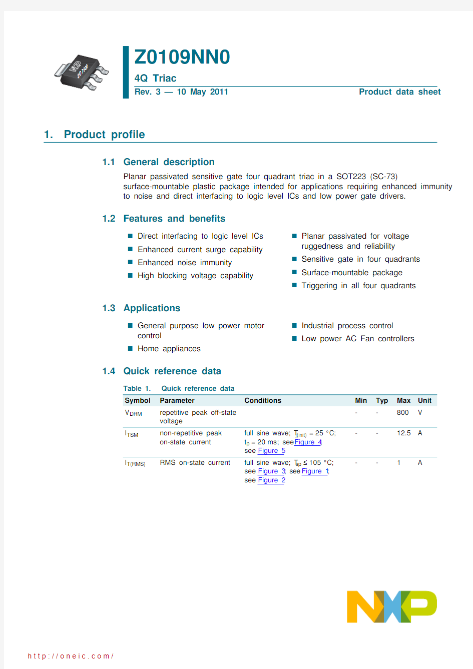
Planar passivated sensitive gate four quadrant triac in a SOT223 (SC-73)
surface-mountable plastic package intended for applications requiring enhanced immunity to noise and direct interfacing to logic level ICs and low power gate drivers.
1.2Features and benefits
Direct interfacing to logic level ICs Enhanced current surge capability Enhanced noise immunity High blocking voltage capability
Planar passivated for voltage ruggedness and reliability Sensitive gate in four quadrants Surface-mountable package Triggering in all four quadrants
1.3Applications
General purpose low power motor control Home appliances
Industrial process control Low power AC Fan controllers
1.4Quick reference data
Z0109NN0
4Q Triac
Rev. 3 — 10 May 2011
Product data sheet
Table 1.Quick reference data Symbol Parameter
Conditions
Min Typ Max Unit V DRM repetitive peak off-state voltage
--800
V
I TSM
non-repetitive peak on-state current full sine wave; T j(init)=25°C; t p =20ms; see Figure 4; see Figure 5
--12.5A
I T(RMS)
RMS on-state current
full sine wave; T sp ≤105°C; see Figure 3; see Figure 1; see Figure 2--1A
2.Pinning information
3.Ordering information
4.Marking
[1]
% = placeholder for manufacturing site code
Static characteristics
I GT
gate trigger current
V D =12V; I T =0.1A; T2+ G+; T j =25°C; see Figure 90.4-10mA V D =12V;I T =0.1A; T2+ G-; T j =25°C; see Figure 90.4-10mA V D =12V; I T =0.1A; T2- G-; T j =25°C; see Figure 90.4-10mA V D =12V;I T =0.1A; T2- G+; T j =25°C; see Figure 9
0.4
-10
mA
Table 1.Quick reference data …continued Symbol Parameter Conditions
Min Typ Max Unit Table 2.Pinning information Pin Symbol Description Simplified outline Graphic symbol
1T1main terminal 1SOT223 (SOT223)
2T2main terminal 23G gate
4
T2
main terminal 2
1
32
4
sym051
T1G
T2
Table 3.
Ordering information
Type number
Package Name
Description
Version Z0109NN0
SOT223
plastic surface-mounted package with increased heatsink; 4 leads
SOT223
Table 4.Marking codes
Type number
Marking code [1]Z0109NN0
109NN0
5.Limiting values
Table 5.Limiting values
In accordance with the Absolute Maximum Rating System (IEC 60134).
Symbol Parameter
Conditions
Min Max Unit V DRM repetitive peak off-state voltage -800V I T(RMS)RMS on-state current full sine wave; T sp ≤105°C; see Figure 3; see Figure 1; see Figure 2
-1A I TSM
non-repetitive peak on-state current
full sine wave; T j(init)=25°C; t p =20ms; see Figure 4; see Figure 5
-12.5A full sine wave; T j(init)=25°C; t p =16.7ms
-13.8A I 2t I 2t for fusing t p =10ms; sine-wave pulse
-0.78A 2s dI T /dt
rate of rise of on-state current
I T =1A;I G =20mA;dI G /dt =100mA/μs; T2+ G+
-50A/μs I T =1A;I G =20mA;dI G /dt =100mA/μs; T2+ G--50A/μs I T =1A;I G =20mA;dI G /dt =100mA/μs; T2- G--50A/μs I T =1A;I G =20mA;dI G /dt =100mA/μs; T2- G+
-20A/μs I GM peak gate current -1A P GM peak gate power -2W P G(AV)average gate power over any 20 ms period
-0.1W T stg storage temperature -40150°C T j
junction temperature
-125
°C
Non-repetitive peak on-state current as a function of pulse width; maximum values
6.Thermal characteristics
Table 6.Thermal characteristics Symbol Parameter
Conditions
Min Typ Max Unit R th(j-sp)thermal resistance from junction to solder point full cycle; see Figure 8
--15K/W R th(j-a)
thermal resistance from junction to ambient
in free air; printed-circuit board mounted: minimum footprint; full cycle; see Figure 6-156-K/W in free air; printed-circuit board mounted: pad area; full cycle; see Figure 7
-
70
-
K/W
7.Characteristics
Table 7.Characteristics
Symbol Parameter Conditions Min Typ Max Unit Static characteristics
I GT gate trigger current V D=12V; I T=0.1A; T2+ G+;
T j=25°C; see Figure 9
0.4-10mA
V D=12V; I T=0.1A; T2+ G-;
T j=25°C; see Figure 9
0.4-10mA
V D=12V; I T=0.1A; T2- G-;
T j=25°C; see Figure 9
0.4-10mA
V D=12V; I T=0.1A; T2- G+;
T j=25°C; see Figure 9
0.4-10mA
I L latching current V D=12V; I G=0.1A; T2+ G+;
T j=25°C; see Figure 10
--15mA
V D=12V; I G=0.1A; T2+ G-;
T j=25°C; see Figure 10
--30mA
V D=12V; I G=0.1A; T2- G-;
T j=25°C; see Figure 10
--15mA
V D=12V; I G=0.1A; T2- G+;
T j=25°C; see Figure 10
--15mA I H holding current V D=12V; T j=25°C; see Figure 11--10mA V T on-state voltage I T=1.4A; T j=25°C;see Figure 12- 1.3 1.6V
V GT gate trigger voltage V D=12V; I T=0.1A; T j=25°C;
see Figure 13
-- 1.3V
V D=800V;I T=0.1A; T j=125°C;
see Figure 13
0.2--V
I D off-state current V D=800V;T j=125°C--0.5mA Dynamic characteristics
dV D/dt rate of rise of off-state voltage V DM=536V; T j=110°C; gate open
circuit; exponential waveform;
see Figure 14
120--V/μs
dV com/dt rate of change of commutating
voltage V D=400V;T j=110°C;
dI com/dt=0.44A/ms; gate open circuit
2--V/μs
分销商库存信息: NXP
Z0109NN0,135
