FEP16DT-G中文资料

FEP16AT-G-FEP16JT -G
TECHNICAL DATA
DATA SHEET 4842,REV.-
FEP16AT-G-FEP16JT-G
ULTRAFAST PLASTIC RECTIFIER
Mechanical Data
? Case: JEDEC TO-220AB molded plastic body over passivated chips ? Terminals: Plated leads solderable per MIL-STD-750, Method 2026 ? Polarity: As marked ? Mounting Position: Any
? Mounting Torque: 5 in. - lbs. max.
? Weight: 0.08 ounce, 2.24 grams Features:
?
Low forward voltage drop ? High surge current capacity ? High current capability ? High reliability
? Superfast recovery times for high efficiency ?
Dual rectifier construction, positive centertap
Mechanical Dimensions: In Inches / mm
TO-220AB
SENSITRON
SEMICONDUCTOR
Green Products
FEP16AT-G-FEP16JT -G
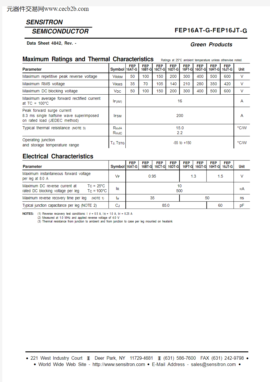
Maximum Ratings and Thermal Characteristics Ratings at 25°C ambient temperature unless otherwise noted.
FEP
FEP
FEP
FEP
FEP
FEP
FEP
FEP
Parameter Symbol 16AT-G 16BT-G 16CT-G 16DT-G 16FT-G 16GT-G 16HT-G 16JT-G Unit Maximum repetitive peak reverse voltage V RRM 50100150200300400500600V Maximum RMS voltage V RMS 3570105140210280350420V Maximum DC blocking voltage
V DC 50
100
150
200
300
400
500
600
V Maximum average forward rectified current I F(AV)16A at TC = 100°C
Peak forward surge current
8.3 ms single halfsine wave superimposed I FSM 200A on rated load (JEDEC method)Typical thermal reisistance (NOTE 3)R ΘJA 15.0°C/W
R ΘJC 2.2Operating junction
T J ,T STG
-55 to +150
°C/W
and storage temperature range
Electrical Characteristics
FEP
FEP
FEP
FEP
FEP
FEP
FEP
FEP
per leg at 8.0 A Maximum DC reverse current at
T C = 25°C
I R 10μA
rated DC blocking voltage per leg
T C =100°C
500
Maximum reverse recovery time per leg (NOTE 1)t rr 35
50
ns Typical junction capacitance per leg (NOTE 2)
C J
85.0
60
pF
NOTES:
(1) Reverse recovery test conditions: I F = 0.5 A, I R = 1.0 A, Irr = 0.25 A (2) Measured at 1.0 MHz and applied reverse voltage of 4.0 V
(3) Thermal resistance from junction to ambient and from junction to case per leg mounted on heatsink
SENSITRON
SEMICONDUCTOR
Data Sheet 4842, Rev. -
Green Products
Maximum instantaneous forward voltage
V F 0.95
1.3 1.5V Parameter Symbol 16AT-G 16BT-G 16CT-G
16DT-G 16FT-G 16GT-G 16HT-G 16JT-G Unit
50?
NONINDUCTIVE
50?
Reverse Recovery Time Characterstic and Test Circuit Diagram
25
5075100125150
175
48121620Ambient Temperature [oC]
A v e r a g e R e
c t i f i e
d F o r w a r d C u r r
e n t , I F [A ]Reverse Characteristics
0 20 40 60 80 100 120 140
0.1
1
10
100
1000
Percent of Rated Peak Reverse Voltage [%]
R
e v e r s e C u r r e n t , I R [m A ]
12
51020
50100
4080120160200Number of Cycles at 60Hz
P e a k F o r w a r d S u r g e C u r r e n t , I F S M [A ]0.40.60.81 1.2 1.4 1.6 1.8
0.01
0.1
1
10
100
Forward Voltage, V F [V]
F o r w a r d C u
r r e n t , I F [A ]
12
5102050100
40
5060
708090100Reverse Voltage, V R
[V]
T o t a l C a p a c i t a n c e , C T [p F ]
Figure 1. Forward Current Derating Curve Figure 2. Non-Repetitive Surge Current
Figure 3. Forward Voltage Characteristics Figure 4. Reverse Current vs Reverse Voltage
SENSITRON
SEMICONDUCTOR
FEP16AT-G-FEP16JT -G
Data Sheet 4842, Rev. -
Green Products
SENSITRON FEP16AT-G-FEP16JT-G