Preparation of photoactive nitrogen-doped rutile
Applied Surface Science 266 (2013) 410–419
Contents lists available at SciVerse ScienceDirect
Applied Surface
Science
j o u r n a l h o m e p a g e :w w w.e l s e v i e r.c o m /l o c a t e /a p s u s
c
Preparation of photoactive nitrogen-doped rutile
D.Dolat a ,?,D.Moszy ′nski a ,N.Guskos b ,c ,B.Ohtani d ,A.W.Morawski a
a
Institute of Chemical and Environmental Engineering,West Pomeranian University of Technology,Szczecin,ul.Pulawskiego 10,70-310,Poland
b
Solid State Section,Department of Physics,University of Athens,Panepistimiopolis,15784,Greece c
Institute of Physics,West Pomeranian University of Technology,Al.Piastow 48,70-311Szczecin,Poland d
Catalysis Research Center,Hokkaido University,Sapporo 001-0021,Japan
a r t i c l e
i n f o
Article history:
Received 5September 2012
Received in revised form 7December 2012Accepted 8December 2012
Available online 20 December 2012
Keywords:Rutile-TiO 2
Photocatalysis N-doping
Semiconductors Catalytic properties
Electronic paramagnetic resonance (EPR)
a b s t r a c t
An easy way of preparing highly N-doped rutile photocatalysts (N–TiO 2/R)in tubular furnace in a constant ammonia (NH 3)?ow at 800–1000?C temperature range is presented.New materials were compared to TiO 2samples prepared at the same temperatures in air atmosphere as well as to the starting https://www.wendangku.net/doc/81678424.html,plete transformation of amorphous and anatase phases to rutile was con?rmed by XRD method.Successful incorporation of relatively high amounts of nitrogen (up to 17%at.),in form of either TiO 2(N),TiO x N y or TiN,on photocatalysts’surface and in their lattice was con?rmed using XPS and XRD analysis.Also presence of Ti 3+was revealed by EPR studies.In contrast to pristine TiO 2,the UV–vis/DR absorp-tion spectra of N-modi?ed photocatalysts extended signi?cantly into the visible light region.Whereas nitrogen concentration as well as visible light absorption were found to increase with increasing mod-i?cation temperature,photocatalytic activity was,on the contrary decreasing.This may be due to the very high nitrogen concentration,obtained at higher modi?cation temperature,as well as the presence of small amount of conductive TiN phase on the N–TiO 2/1000?C photocatalyst surface.The arti?cial solar light activity of new photocatalysts after thermal treatment in NH 3increased in comparison to starting material,due to nitrogen modi?cation and presence of Ti 3+ions.Activity under UV(-vis)light,though,decreased after modi?cation procedure,probably due to smaller surface areas of new photocatalysts and complete anatase to rutile transformation.
? 2012 Elsevier B.V. All rights reserved.
1.Introduction
One of the most challenging requirements for modern water puri?cation systems is to degrade hazardous organic pollutants.One of the most effective and relatively cheap method seems to be advanced oxidation processes (AOPs)that generally involve gener-ation of very powerful and non-selective oxidizing agent –hydroxyl radical (OH*),which destroys organic waste [1–3]via its miner-alization,which eventually leads to CO 2and H 2O formation.For the purpose of AOPs different semiconductors as heterogeneous photocatalysts are used.Recently,the most commonly used semi-conductor is TiO 2as a non-toxic,cheap material of relatively high chemical stability [4].In order to enhance the photocatalytic activ-ity of TiO 2under visible light irradiation,what is essential from the economical point of view,many different ways of modi?cation have been widely studied.Thus researchers focused on TiO 2metal doping using iron [5–7],nickel [8,9],vanadium [10,11],chromium [12,13],platinum or cobalt [14,15].
?Corresponding author.Tel.:+48914494277;fax:+48914494686.E-mail address:ddolat@https://www.wendangku.net/doc/81678424.html,.pl (D.Dolat).
Nevertheless,titanium dioxide metal doping often leads to the recombination centers increase [16]and can be very expensive.For this reasons other ways of TiO 2modi?cation have been employed.The most promising seems to be non-metal modi?cation,using car-bon [17,18],sulfur [19],phosphorous [20],and nitrogen [21–23].Doping with nitrogen is advantageous because nitrogen can be eas-ily incorporated by annealing the sample in a nitrogen-containing gas ?ux,or by ion implanting nitrogen into the TiO 2[24].The behav-ior of N in TiO 2has been widely discussed [21,25–28],but the fundamental mechanism underlying the visible-light absorption remains unclear [29].It is generally accepted that the visible-light transitions involve electrons from N-related states migration to the conduction band.Nonetheless,whether the predominant active species are N atoms at interstitial sites or on substitutional O sites (N O ),and whether the behavior of N in rutile is different from that in anatase are still open issues.There are only relatively few papers describing rutile nitrogen-modi?cation in comparison to the number of publications concerning N-doped/modi?ed anatase materials.Most of the experimental works has been,so far,per-formed using either anatase or mixed anatase/rutile TiO 2powder systems [24].
Irie et al.[25]prepared TiO 2?x N x (x =0,0.0050,0.011,0.019)powders by titanium dioxide annealing under NH 3?ow at 550,
0169-4332/$–see front matter ? 2012 Elsevier B.V. All rights reserved.https://www.wendangku.net/doc/81678424.html,/10.1016/j.apsusc.2012.12.048
D.Dolat et al./Applied Surface Science266 (2013) 410–419411
575,and600?C and investigated the quantum ef?ciency of decom-posing gaseous2-propanol(IPA)under the same absorbed photon number of visible or UV light.They found out that nitrogen substi-tuted some of the oxygen sites in TiO2,forming a narrow N2p band above the valence band.Wang et al.[30]prepared N-doped TiO2 (anatase/rutile)by thermal treatment of commercial P25TiO2in NH3?ow at400–700?C https://www.wendangku.net/doc/81678424.html,ter also Wang et al.[31]obtained series of photocatalysts by annealing different precursors(nan-otubular titanic acid,raw P25TiO2and novel TiO2)in?owing NH3 at600?C for4h in order to study the origin of the visible light absorption and photoactivity.They proved that the visible light photocatalytic activity of N-doped anatase TiO2is co-determined by the formation of SETOV(single-electron-trapped oxygen vacan-cies)and the presence of‘doped-N’.The absorption edge observed in the visible spectral region was closely related with SETOV,while ‘doped-N’played a role in preventing photogenerated electrons and holes from recombination,resulting in visible light photocatalytic activity.
Theoretical investigation[32]demonstrated quite different effects of nitrogen doping on electronic structure of anatase and rutile,i.e.,downward shifting of valence band maximum indicating increased oxidation power of holes in nitrogen-doped rutile TiO2. Meanwhile,surface reconstruction of rutile by nitrogen doping was also observed experimentally[33].These unique properties associated with nitrogen-doped rutile TiO2may greatly alter its photocatalytic activity.Di Valentin et al.[32]have con?rmed very different photoactivity results for N-doped anatase and rutile. According to their theoretical studies,for anatase samples,the presence of substitutionally bound nitrogen causes a decrease in the absorption band edge,while in rutile,the opposite-increase in absorption band edge.However,on the contrary to their predic-tions,Liu et al.[34]have prepared two series of nitrogen-doped TiO2samples with different ratios of anatase to rutile phases by milling the mixture of P25TiO2and C6H12N4in air and gaseous NH3atmosphere,respectively.It was found that nitrogen-doped TiO2with higher content of rutile phase demonstrated higher pho-tocatalytic activity in photodegrading pollutant rhodamine B under both UV light and visible light irradiation( >420nm).
The aim of this work was to obtain photoactive rutile-TiO2by nitrogen doping.We wanted to determine whether ef?cient N-doping is possible in case of rutile titanium dioxide and how this modi?cation can in?uence its photocatalytic activity under differ-ent types of irradiation.The relation between nitrogen content and the new materials’photocatalytic activity as well as the N-modi?cation origin has been studied.For this purpose two series of rutile-TiO2materials obtained by thermal treatment of pristine amorphous titanium dioxide at800,900and1000?C in tubular fur-nace were prepared.First group was annealed for4h in ammonia (NH3)?ow,the second one also for4h in the air?ow.The pho-tocatalytic activity was studied under UV(-vis)(of strong UV light intensity)and arti?cial solar light irradiation.The photocatalysts’crystallite and surface structure,light absorption abilities as well as magnetic response of N–TiO2/rutile have been studied.Finally,the difference between anatase and rutile response to N-modi?cation and its in?uence on these phases photocatalytic behavior is here discussed.
2.Materials and methods
2.1.Materials
Water suspension of commercial,amorphous titanium dioxide (TiO2/A)from sulfate technology,containing ca.8%of residual sul-furic acid relatively to TiO2content,supplied by Chemical Factory “Police”S.A.(Poland)with BET surface area of238m2/g was used as a pristine material for the synthesis of N-modi?ed rutile TiO2 photocatalysts.Ammonia(NH3)was used in photocatalysts prepa-ration process was supplied by Messer(99.85%).Phenol was used as the model organic pollutant for the evaluation of the photocata-lysts’activity.High purity water for the photocatalytic experiments and sample analysis was produced by a Millipore Felix Advantage water puri?cation system.Modi?cation procedure:Modi?cation of TiO2was conducted with gaseous ammonia at the temperatures which guaranteed complete anatase and amorphous phase trans-formation to rutile(800–1000?C).The crude TiO2from sulfate technology was modi?ed with gaseous ammonia(NH3)as follows.
A de?ned amount–about20g,of water suspension of TiO2,con-taining ca.35%of titanium dioxide,was placed in the melting pot and introduced into the tubular furnace.Then samples were cal-cined at800–900–1000?C in NH3or synthetic air atmosphere for 4h(samples prepared in air atmosphere were marked as TiO2/800, TiO2/900,TiO2/1000while those obtained in ammonia?ow as: N–TiO2/800,N–TiO2/900,N–TiO2/1000).After heating the furnace was cooled down for about4h to the room temperature,then at room temperature?ushed with argon for15min.Subsequently, dried for24h at105?C in a muf?e furnace.
3.Experimental
3.1.Photocatalysts characterization
The crystalline structure of the photocatalysts was characterized by means of X-ray powder diffraction(XRD)analysis(X’Pert PRO Philips diffractometer)using Cu K?radiation.The X-ray photoelec-tron spectra were obtained using Mg K?(hv=1253.6eV)radiation with a Scienta SES2002spectrometer operating at constant transmission energy(E p=50eV).The spectrometer was calibrated by using the photoemission line Ag3d5/2E B=368.3eV.Data processing involved background subtraction by means of Shirley pro?le and a curve-?tting procedure(a mixed Gaussian–Lorentzian function was employed)based on a least-squares method(soft-ware CasaXPS).The quantitative composition of the surface was calculated assuming homogeneous distribution of elements.The powder samples were loosely placed into the sample holder.The analysis chamber during experiments was evacuated to better than1×10?9mbar.Charging effects were corrected by using the O1s peak with E B?xed at530.0eV.The measurements of mag-netic resonance spectra were performed on a conventional X-band ( =9.4GHz)Bruker E500spectrometer with100kH magnetic ?eld modulation.Sample containing around20mg of powder was placed in4mm diameter quartz tube.The FMR thermal studies were performed in the temperature range4–300K using an Oxford helium-?ow cryostat.The photocatalysts were also characterized by UV–vis/DR technique using a Jasco V-650spectrophotometer (Japan)equipped with an integrating sphere accessory for diffuse re?ectance spectra acquisition(BaSO4was used as a reference).The N2-BET speci?c surface area of the materials was measured at77K using an Quadrasorb SI(Quantachrome Instruments,USA)instru-ment.Prior to analyses,each sample was degassed at105?C for 24h under high vacuum.The values of the speci?c surface areas (S BET)were determined using multi-point analysis of adsorption isotherms applying Brunauer–Emmet–Teller(BET)equation.The total organic carbon(TOC)measurements were conducted in Ana-lytic Jena Multi N/C3100(Germany).
3.2.Experimental procedure
The photocatalytic activity of new materials was studied under UV(-vis)and arti?cial solar light irradiation.Photocatalytic activi-ties of the samples under both types of irradiation were evaluated
412 D.Dolat et al./Applied Surface Science 266 (2013) 410–419
0 10000
20000 30000 40000 50000 60000 70000 200
300
400
500
600
700
800
I r r a d i a t i o n i n t e n s i t y (W /m 2)
Wavelength (nm) 0 20000
40000 60000 80000 100000 120000 200
300 400 500 600 700
800
I r r a d i a t i o n i n t e n s i t y (W /m 2)
Wavelength (nm)
a
b
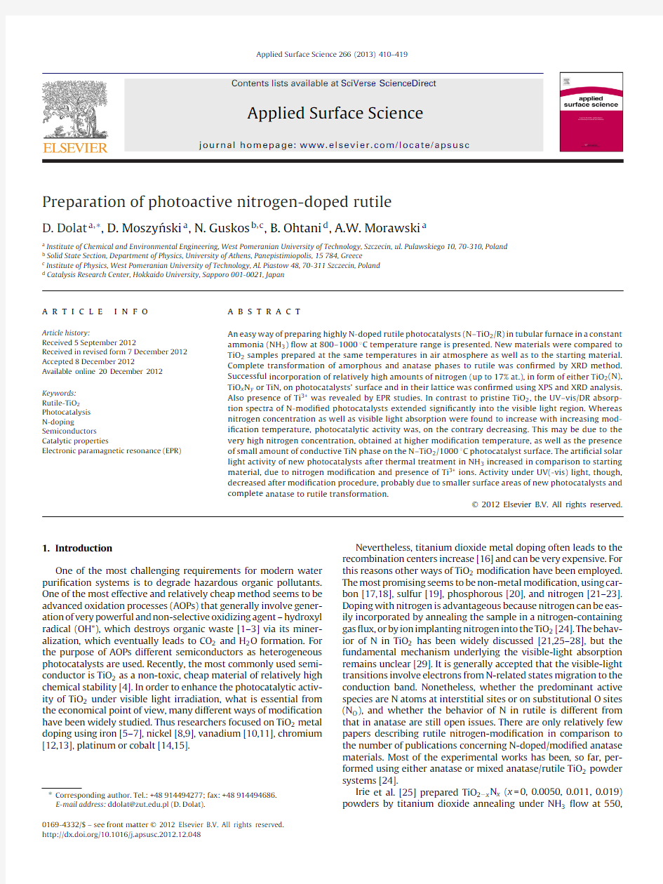
Fig.1.Emission spectrum of UV–vis lamps (a)and arti?cial solar light lamp (b)used for photocatalytic activity measurements processes.
by oxidative decomposition of phenol under air in aqueous solu-tions.Photocatalytic reaction was performed in a glass beaker with magnetic stirring at 500rpm.A photocatalyst (100mg)was suspended in an aqueous solution (500cm 3)of 10ppm phenol concentration.The irradiation of the solution under UV(-vis)light was operated using a group of 6lamps with power of 20W each (Phillips)with the radiation intensity of 134.38W/m 2visible and 132.45W/m 2UV (the measurement of irradiation intensity was done in 15cm distance from the light source).The emission spec-tra of these lamps are presented in Fig.1a.Phenol concentration changes were measured using UV–vis spectrometer (Jasco V-630,Japan)by measuring the absorbance of phenol solution at a max-imum wavelength of 270nm during the whole irradiation time in 0.5h intervals.The mineralization rate was measured using TOC Multi N/C 2000analyzer (Analytik Jena,Germany).
The irradiation of the solution under arti?cial solar light was operated using halogen lamp with a power of 70W (Philips)with the radiation intensity of about 883W/m 2visible and 0.6W/m 2UV (see the emission spectra in Fig.1b).The solution irradiation time was 24h.The concentration of phenol in the solution after the photocatalytic process was also determined by means of the UV–vis spectrometer,as well as by measuring the concentration of TOC reminded in the solution.Prior to all this measurements the solution was centrifuged and ?ltered through a membrane ?lter with 0.45?m pore diameter.The ?lter material did not retain phe-nol.As one can see for both types of irradiation the photocatalytic processes were performed at different time conditions and using different irradiation sources.This is simply due to the fact that the 24-h irradiation time is essential for comparison of activities in the solar light since the photocatalytic oxidation under solar is slower
than in case of UV–vis light irradiation.In case of UV–vis irradiation the 5-h process is suf?cient for the materials’photoactivities eval-uation.What is more,the intensity of visible light emitted by the employed solar lamp is 6.5times higher than the intensity of visi-ble light emitted by the employed UV–vis lamp,at the same time the intensity of UV light emitted by UV–vis lamp is 220(!)times higher than in case of the solar lamp.Therefore,we can practically assume no contribution of visible light to the UV–vis activity and almost no contribution of UV light to the solar light activity of the materials.Also,our main goal was to compare activities of the new materials under UV–vis and solar light irradiation separately,with the focus on the solar light activity.
4.Results and discussion
4.1.XRD,BET
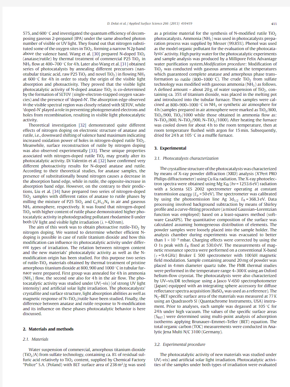
In Table 1the BET speci?c surface areas of prepared materials are presented.The temperature modi?cation in?uenced signi?cantly surface areas of the new photocatalysts,however,the obtained results 12–19m 2/g and 4–8m 2/g for N–TiO 2/rutile and TiO 2/rutile samples,respectively do not differ markedly between the new materials prepared in the same atmosphere.It can be concluded that in the temperatures above 800?C the BET surface area do not depend strongly on the modi?cation temperature.Neverthe-less,one can see clearly that the BET SSA of samples prepared in ammonia atmosphere are always higher than for correspond-ing samples obtained in the air atmosphere.This brings us to a simple conclusion that the ammonia atmosphere may slightly sta-bilize the photocatalysts’surfaces from sintering.Fig.2shows the X-ray diffraction patterns of the original photocatalysts precursor TiO 2/A together with N–TiO 2/rutile samples prepared by heating at different temperatures.As expected,it can be observed that the modi?cation at 800–1000?C caused a signi?cant increase in the amount of rutile phase content (100%)and a complete disap-pearance of both anatase and amorphous phase for both types of preparation conditions in air (not presented here)and ammonia ?ow.The mean crystallite size exceeds 100nm,and cannot be cal-culated using XRD method by Scherer’s equation.Apart from rutile phase re?exes (R)also other,intense re?exes (N)can be seen in the patterns of N–TiO 2/rutile samples.These re?exes suggest for-mation of a new phase in the photocatalysts’structure.This phase was assigned,with the highest probability,to the mixture of differ-ent TiO x N y phases with various,dif?cult to distinguish x ,y values,identi?ed by comparison of the measured XRD patterns with the JCPDS cards (nos.04-001-9292;04-002-0428;04-002-0430and 04-002-0431).
These results suggest strong,structural N-modi?cation of N–TiO 2/rutile photocatalysts.The intensity of (N)re?exes increases with the increasing annealing temperature.The partial substitu-tion of oxygen atoms from TiO 2lattice with nitrogen atoms during modi?cation process can be concluded,and is supported by XPS results which will be discussed later.Due to only slightly larger ionic radius of N than that of O,replacing an O atom with a N atom only induces slight structural changes and is preferable for nitrogen doping.Cheung et al.[24]described the growth and properties of well-de?ned epitaxial TiO 2?x N x rutile.Epitaxial growth of TiO 2and TiO 2?x N x rutile prepared under anion-rich conditions is accompa-nied by Ti indiffusion,leading to interstitial Ti,which is a shallow donor in rutile.Both Han et al.[35]and Cheung et al.[24]sug-gested extended optical absorption well into the visible light due to nitrogen for oxygen substitution.Ti–N hybridized states fall in the gap just above the valance band which mainly originate from N 2p orbitals and are expected to facilitate optical absorption in the visible-light region.
D.Dolat et al./Applied Surface Science266 (2013) 410–419413 Table1
BET surface area,nitrogen atomic concentration,nitrogen to titanium ratio as well as TOC removal after5and24h of phenol decomposition under UV–vis and arti?cial solar light,respectively.
Photocatalyst BET SSA(m2/g)Surface nitrogen concentration(at.%)[N]/[Ti]ratio TOC removal a(%)TOC removal b(%) TiO2/A238––732
TiO2/800?C8––00.5
TiO2/900?C7––00
TiO2/1000?C4––00
N–TiO2/800?C16 6.70.25247
N–TiO2/900?C1990.37195
N–TiO2/1000?C1217.20.64163
a After24h of phenol decomposition under arti?cial solar light irradiation.
b After5h of phenol decomposition under UV–vis light.
It is also worth mentioning that the total amount of sulfuric acid was removed from the photocatalysts structure and surface during both modi?cation processes.Neither XRD nor,discussed in next paragraph,XPS studies detected traces of the remaining sulfur.In case of N-modi?cation procedure–calcinations in ammonia atmo-sphere this is due to the phenomenon that was described in our previous study[36]:during the modi?cation,while the reactor was being heated up,the entire amount of sulfuric acid from the crude TiO2structure reacted with gaseous ammonia to give ammonium sulfate[(NH4)2SO4]and thiosulfate[(NH4)2S2O3]in the temper-ature range of100–350?C.These compounds were being carried away in the NH3?ow and subsequently formed deposits in the colder parts of the reactor.These deposits were also characterized by means of XRD for con?rmation[36].In case of samples calcined without ammonia–in air atmosphere,the residual sulfuric acid was removed by transformation into gaseous state.The sulfuric acid in titanium dioxide is present in the form of titanyl sulfate (TiOSO4)which decomposes to SO3and TiO2in the temperatures above600?C.
4.2.XPS
XPS analysis of the N–TiO2/rutile samples under study shows that their surface undergoes a substantial change during the nitrid-ing processes.In Fig.3the XP spectra of Ti2p lines obtained for pure,untreated TiO2as well as TiO2samples nitrided in ammonia atmosphere at800?C,900?C and1000?C,respectively,are shown. The XP spectrum of untreated TiO2/A sample is identical with the ones presented in the literature[37–39]with the maximum of the XPS Ti2p3/2peak located at458.8eV and the spin–orbit splitting component separated https://www.wendangku.net/doc/81678424.html,paring to the untreated TiO2the Ti2p XP spectrum of the TiO2sample treated in ammonia at 800?C exhibits a slight change of the line pro?le:Ti2p3/2peak is somewhat broadened(from1.2eV to1.5eV),though,no position shift is discerned.Additionally at low binding energy side of the Ti 2p3/2peak a weak structure between454eV and457eV appears. In the pro?le of XPS Ti2p line obtained for N–TiO2/900?C sam-ple changes are more evident.The full width in half maximum (FWHM)of Ti2p3/2peak increases to1.9eV still without shift in its position and the structure at the low binding energy side of the peak is stronger.The change of the XPS Ti2p line shape is the strongest for the N–TiO2/1000?C sample.The main Ti2p3/2 peak becomes very broad(FWHM=2.6eV)and the small shift of its maximum to458.5eV is observed.The shoulder at the low binding energy is very intense.Moreover,a discernible structure appears between Ti2p3/2and Ti2p1/2spin–orbit splitting components at about461eV.
In Fig.4the XP spectra of N1s peak for samples nitrided at800?C, 900?C and1000?C are shown.The XP spectra obtained for the sam-ples prepared at800?C and900?C are similar.The main maximum is placed at396.1eV and it is accompanied with a small shoulder at about399eV.The former position of N1s peak is ascribed in the literature to the different states of atomic nitrogen associated with the presence of oxygen[40],titanium oxynitride[41,42]or interstitial nitrogen[43].The small feature at399eV can originate from C N bonds usually coming from carbon contamination.How-ever some reports suggest that this position can be associated with oxynitrides[42].The XPS N1s peak for N–TiO2/1000?C sample is slightly different.The maximum of this line is shifted to396.7eV and corresponds well with the XPS spectra of TiN[40,42].
Table1contains the concentration of the nitrogen and oxygen atoms,as well as nitrogen to titanium concentration ratio,in
the Fig.2.Powder X-ray diffraction patterns of starting the TiO2/A and the N–TiO2/rutile photocatalysts measured with Cu K?.
414 D.Dolat et al./Applied Surface Science 266 (2013) 410–
419
Fig.3.The XP spectra of Ti 2p lines for starting TiO 2/A and the N–TiO 2/rutile photo-catalysts.
surface layer of the samples estimated assuming a homogeneous distribution of N atoms in the analyzed volume.The results indicate that the concentration of nitrogen atoms as well as the [N]/[Ti]ratio increase with the temperature.
The XPS analysis depicted above shows that in case of the sam-ples treated in ammonia an incorporation of nitrogen atoms into the TiO 2takes place.The preliminary analysis of the XPS Ti 2p and N 1s peaks suggest the presence of titanium oxynitrides (TiO x N y )or titanium nitride (TiN)(in case of N–TiO 2/1000?C sample)in the super?cial layer of the materials.However,due to complexity of XPS Ti 2p spectra the detailed description of chemical and structural composition of the transformed material is not possible without thorough analysis of the XPS pro?les.Therefore an effort has been made to deconvolute the experimental XPS lines of Ti 2p states obtained for all studied samples.Before a peak ?tting procedure the background of scattered electrons has been removed from all spectra applying a Shirley-type function.Then a peak model con-sisting of four peaks of mixed Gaussian–Lorentzian character has been applied to all four XPS Ti 2p experimental spectra.The peak model is based on the preliminary analysis of the data and assumes the following synthetic components:(a)TiO 2-pure,non-modi?ed TiO 2,(b)TiO 2(N)–titanium dioxide with nitrogen atoms inter-stitially dissolved in the lattice,(c)TiO x N y –titanium oxynitrides formed under the in?uence of ammonia,and (d)TiN –titanium nitride being a result of total nitridation of TiO 2.The initial pos-itions of the synthetic peaks were taken from the literature reports and are as follows:(a)TiO 2–the Ti 2p 3/2peak in position of 459eV (2),(b)TiO 2(N)–the Ti 2p 3/2peak in position of 458.3eV (2),
(c)
Fig.4.The XP spectra of N 1s peak for N–TiO 2/rutile samples.
TiO x N y –the Ti 2p 3/2peak in position of 456.4eV [44],and (d)TiN –the Ti 2p 3/2peak in position of 455eV (8).Each Ti 2p 3/2compo-nent is accompanied by an appropriate Ti 2p 1/2spin–orbit splitting component separated by approximately 5.7–5.8eV.The peak ?t-ting procedure based on the model resulted in a reasonably good ?t to all experimental XPS Ti 2p lines supporting the choice of the peak-?t model.The components obtained from the procedure are presented in Fig.3.
The results coming from the deconvolution of the data con?rm that the sample not treated in ammonia consists of pure TiO 2.The TiO 2component is present in all nitrided samples though its inten-sity in the XPS spectra decreases with increasing temperature of the process.The intensity of nitrogen-bearing components:TiO 2(N),TiO x N y and TiN,rises with the temperature indicating increasing conversion degree of TiO 2into nitrided species.This observation is in line with the XRD analysis showing the formation of TiO x N y and TiN phases.
Considering the conditions of the nitriding process,the ?ne-crystalline form of the material as well as the results of XPS study a multi-layer model of the products obtained upon nitriding is pro-posed.It is supposed that at the surface of the grains,titanium nitride (TiN)is formed.Below TiN a titanium oxynitride layer of gradually changing stoichiometry is present.Deeper,where the amount of nitrogen atoms is not suf?cient to force a substitutional incorporation of nitrogen into titanium oxide a volume of TiO 2with interstitial nitrogen is formed.The core of the grains is supposedly pure TiO 2barely affected by nitrogen reacting with the outer sur-face of the material.
D.Dolat et al./Applied Surface Science 266 (2013) 410–419
415
-50
d "/d H (A r b . u n i t s )
Magneti c field H (G)
Fig.5.Temperature dependence of the EPR spectra for N–TiO 2/800?C sample.
4.3.EPR
Fig.5presents the EPR spectra of sample N–TiO 2/800?C at vari-ous temperatures.A very intense and asymmetric single resonance line was recorded at low temperature regions.A strong temper-ature dependence of the intensity of FMR spectra is observed to be signi?cantly less intense over 210K.This resonance line is cen-tered at g eff =1.948(1)with linewidth of H pp =32.0(2)G and these parameters are almost the same at all temperatures.The spectra can be arising from trivalent titanium ions near surface [45–47].In Fig.6the EPR spectra of samples N–TiO 2/800,N–TiO 2/900and N–TiO 2/1000at room temperature are given.These resonance lines are centered at g eff =1.948(1),g eff =1.959(3)and g eff =1.949(3)for samples TiO 2/800,TiO 2/900and N–TiO 2/1000,respectively where the linewidth are between 8G and 10G.These resonance lines could be formed by Ti 3+on the TiO 2surface.The titanium oxide is a semi-conductor and the electron conductivity interacts on the intensity of the EPR spectra after so-called skin effect [48].With increas-ing temperature skin depth of penetration microwave radiation is decreasing.
The Ti 4+ions in TiO 2can be reduced to Ti 3+ions by reacting with reducing agent at high temperatures.It is well known that NH 3decomposes into N 2and H 2at around 550?C.Up to now,the most synthesis methods for the preparation of titanium dioxide contain-ing Ti 3+ions were carried out by reducing TiO 2with H 2gas in a closed chamber.These methods are expensive,and the reactions are dif?cult to be controlled.The reduction reaction is accompa-nied with introduction of oxygen vacancies into the structure and formation of non-stoichiometric TiO 2with oxygen vacancy.Also the defects on the TiO 2(110)surface are easily created by thermal annealing of the surface at high temperatures.Thermally created defects have been recognized extensively in the literature as point defects.Macroscopically,the presence of oxygen vacancies creates an overall reduced state of the TiO 2crystal,both in the bulk and on the surface.Upon the annealing,the creation of defects within the bulk is associated with the creation of color centers and Ti 3+interstitial ions [49].It has been reported that the vacancy creation occurs by the use of thermal annealing above about 600K [53]and results in the energy state of the oxygen vacancy [50,51].The for-mation of oxygen vacancy is due
to the upkeep of charge balance in the crystal after the reduction of Ti 4+to Ti 3+.
The oxygen vacancies formed in TiO 2bulk during heat-treatment
in ?owing NH 3can be hypothetically divided into three categories:(1)SETOV –single-electron-trapped oxygen vacancy,(2)dual-electrons-trapped oxygen vacancy,and
(3)
3330335033703390
Magnetic Field H (G)
3330335033703390
Magnetic Field H (G)
3330335033703390
Magnetic Field H (G)
Fig.6.The EPR spectra of the N–TiO 2/rutile samples at room temperature (RT).
oxygen vacancy without electron.The SETOV in N-doped TiO 2may show triplet g value ESR signals (g =1.987,2.004and 2.024)and were not detected in the analyzed N–TiO 2samples.The latter two types of oxygen vacancies do not produce ESR signals [30]which means the con?rmation of their presence is not possible by means of ESR studies.Wang et al.[30,31]have suggested that visible light absorption of TiO 2samples can be caused by:the SETOV creation and/or anatase to rutile transformation.In this case we clearly deal with the later situation.It is a fact that the visible light absorp-tion is not a sole factor determining the visible light photocatalytic activity of titanium dioxide.Thus,apparent visible light photo-catalytic activity is obtained after TiO 2doping with N [52].This indicates that the visible light photocatalytic activity of N-doped TiO 2is co-determined by two factors:the visible light activity derived from either formation of SETOV or anatase to rutile phase transformation and the presence of ‘doped-N’.No visible light pho-tocatalytic activity will be obtained unless the two factors function simultaneously.
416 D.Dolat et al./Applied Surface Science 266 (2013) 410–
419
020406080100200400600800
A b s o r b a n c e
Wavelength (nm)
(a)
20406080
100
200400600800
A b s o r b a n c e
Wavelength (nm)
(b)
020406080
100200400600800
A b s o r b a n c e
Wavelength (nm)
(c)
Fig.7.UV–vis/DRS spectra of N–TiO 2/rutile samples together with TiO 2/A for comparison.
Moreover,the oxygen vacancies creation in rutile TiO 2may play an essential role in controlling the adsorption of O 2,where O 2molecules seek the vacancy defect sites for non-dissociative adsorption,producing the superoxide species,O 2?.This takes place by O 2interaction with surface Ti 3+sites which are produced by thermal reduction of the surface by removal of surface O 2?anions.Adsorbed O 2molecules can also act as electron scaven-gers when electron–hole pair creation occurs by photoexcitation in the TiO 2,also producing superoxide O 2?species.Adsorbed O 2?may interact with photogenerated holes,which results in the desorption of O 2.Finally,the adsorbed O 2,when excited by electron–hole pair production in the TiO 2,acts as an oxidizing agent for organic molecules on the surface of the TiO 2[53].Oxygen vacancies inevitably exist on the surface of n-type rutile TiO 2semi-conductor,in particular nano-sized particles with large exposed surfaces.Meanwhile,nitrogen doping can introduce additional oxygen vacancies in order to keep the charge balance of the sys-tem [34].The possible downward shifted valence band maximum in nitrogen-doped rutile TiO 2predicted by theoretical investigation [32]can give rise to stronger oxidative holes in the valence band,which can better involve in directly attacking substrates or combin-ing with surface adsorbed water and hydroxyl groups into hydroxyl radicals.
4.4.UV–vis/DR
In Fig.7the UV–vis/DR spectra of the N-modi?ed materials are presented.The N–TiO 2/rutile photocatalysts signi?cant visible light absorption is obvious from the spectra given.The N-modi?ed samples absorb the whole spectrum of light and this is in accor-dance to the fact that all the obtained N–TiO 2/rutile samples were almost black.Unfortunately extraction of the absorption edge of the band-gaps is rather dif?cult in this case due to the fact that photocatalysts are black.The reason for the color –black,may be due to non band-gap absorption (e.g.due to the lattice defects)and the fact that absorption of long visible-light wavelengths overlaps the band-band transition absorption.Nevertheless,it can be seen that the visible light absorption slightly increases with increas-ing modi?cation temperature in case of N–TiO 2/rutile samples.Simple conclusions can be drawn on these basis:(1)it is possi-ble to prepare pure TiO 2/rutile samples with strong visible light absorption by annealing the commercial mixture of amorphous and anatase TiO 2in synthetic air ?ow in tubular furnace,(2)the higher temperature of photocatalysts modi?cation in ammonia ?ow and thus,as shown above,higher nitrogen content in N–TiO 2/rutile photocatalysts structure the stronger absorption in the visible light region.Experimental studies conducted by Irie et al.[54]showed that doping anatase TiO 2with substitutional N to the O sites in TiO 2improves optical absorption in the visible-light region [54].The same phenomenon was observed in the N-doped materials of mixed anatase and rutile phases,in the forms of thin ?lms [55],
powders [25,56],or nanoparticles [57].The increase in absorbance at wavelengths greater than 550nm may correspond to Ti 3+ions presence [58].Batzill et al.[33]suggested that nitrogen incorpora-tion is signi?cantly stabilized by simultaneous O vacancy creation [32,59].However,no experimental studies concerning pure rutile phase were reported so far.
Some of the theoretical studies,though,predicted a visible light absorption increase for TiO x N y rutile [32].Diwald et al.[26]con-cluded that N is present as an interstitial bound to hydrogen when TiO 2rutile is treated with NH 3and that this speciation gives rise to enhanced optical absorption at photon energies below the rutile band-gap.Liu et al.[34]showed that the presence of N O (substitu-tional N to O doping)in TiO 2structure may lead to sub-band-gap optical transitions centered at 2.46eV for rutile.They also sug-gested that high nitrogen doping,with which we are certainly dealing in this case,can eventually lead to incorporation of (N 2)O (substitutional N 2to O doping).What is more,the presence of small amount of TiN species on the N–TiO 2/100photocatalyst surface was revealed.TiN,as described above,gives XPS binding energy of 396.7eV and appeared only for the sample modi?ed at 1000?C.This kind of TiO 2modi?cation with TiN surface species has been reported earlier.Diwald et al.[26]described N (1s)with binding energy of 396.7eV introduction into the TiO 2bulk via heat treat-ment in NH 3at 870K,resulting in reducing the threshold photon energy for photochemistry from 3.0eV to 2.4eV.Nevertheless,in this case we deal with different model of nitrogen implantation.In our study the TiN phase is placed practically only on the photocata-lysts surface.TiN is a conductor and its’presence on the surface may cause changes in optical properties of the material.What is more TiO 2photocatalytic activity changes with mixed phase vs.single phase.Its in?uence on the photocatalytic activity of this sample will be later discussed.
The results presented in this paragraph,again,con?rmed the successful nitrogen doping of rutile TiO 2photocatalysts resulting in appreciable visible light absorption.It was proved,by experi-mental studies,that nitrogen incorporation in rutile TiO 2,similarly to anatase,results in the increase of visible light absorption.These light absorption increase,though,is way more advanced in case of rutile than anatase,due to higher modi?cation temperatures.It is also worth mentioning that the nitrogen concentration in all new N–TiO 2/rutile materials was relatively high in comparison to anatase phase modi?cation ef?ciency reported in the literature [31,60].
4.5.Photocatalytic activity
The photocatalytic activity of new materials was tested as described in experimental section and the obtained results are presented in Table 1.It can be seen that the thermal modi?cation of starting material –TiO 2/A with gaseous ammonia resulted in appreciable photoactivity increase under arti?cial solar light
D.Dolat et al./Applied Surface Science 266 (2013) 410–419
417
5
1015
20
T O C r e m o v a l a f t e r 24 h u n d e r A S L i r r a d i a t i o n [%]
nitrogen conce
ntration (%)
0123
4567
85
1015
20
T O C r e m o v a l a f t e r 5h u n d e r U V -v i s l i g h t i r r a d i a t i o n (%)
nitrog en con centration (%)
Fig.8.The dependence of photocatalytic activity of new materials under UV–vis (a)and arti?cial solar light (b)on nitrogen concentration.
irradiation,whereas its modi?cation performed in the synthetic
air ?ow supplied us with completely inactive (under arti?cial solar light irradiation)pure rutile samples with the standard band-gap energies of 3.0eV.The UV(-vis)light activity decreased for all new samples after modi?cation in comparison to the starting material (see Table 1).What is more,materials prepared in air atmosphere present no photocatalytic activity under any type of irradiation applied.In Fig.8(a)and (b)the dependence of photoactivity of prepared samples on the nitrogen concentration are presented.An obvious relation between nitrogen concentration in N–TiO 2/rutile structures and new materials’photoactivity can be observed and,what is more,the relation is almost identical for both types of irradiation used.Thus,the higher nitrogen concentration the lower photocatalytic activity of obtained samples,however,the higher visible light absorption.These results are in accordance with previous observation made by Ohtani and described elsewhere [60]–it was proved that the photocatalytic activity under the UV-light irradiation (290and 350nm)decreases with increasing nitrogen content.What was also pointed out in the paper was that the absorbance in the visible-light region increases with increasing nitrogen concentration in obtained samples.The visible light absorption increase,however,was not tantamount to increase in the visible light photocatalytic activity.
The BET speci?c surface areas as well as Ti 3+signal inten-sities recorded by EPR studies do not differ markedly enough between presented N-doped samples to be acknowledged as main factors in?uencing the photocatalytic activity.That is why we state that the new materials’solar and UV(-vis)light activities depend mainly on nitrogen concentration.With increasing temper-ature,nitrogen concentration increases signi?cantly up to 17at.%,which gives nitrogen to titanium rate of about 0.64.As discussed in XPS section as a result of N-doping on photocatalysts sur-faces TiO 2(N),TiO x N y as well as small amount of TiN are formed.Titanium nitride is a conductor,and its presence on the sur-face of the photocatalysts may have caused the signi?cant drop in N–TiO 2/1000?C sample photocatalytic activity.For this reason photocatalyst with the highest nitrogen concentration and better visible light absorption is not the one with the highest visible light activity.Simple conclusion then can be drawn here from these results that the presence of even small amount of TiN phase on the photocatalysts’surface has negative in?uence on their photo-catalytic activity.
The decrease observed in UV(-vis)light activity of new sam-ples after modi?cation process in comparison to the starting TiO 2/A may result from two contributing factors.First,signi?cant changes in BET surface areas of the samples before and after calcination procedure.It is obvious that during the calcinations at high temper-atures the photocatalysts’particles became sintered what resulted in way smaller surface areas negatively in?uencing the UV light applications.Second,the modi?cation process caused complete transformation of anatase phase to rutile [61,62].
5.Conclusions
A series of N-doped rutile photocatalysts was obtained by thermal treatment of a commercial amorphous titanium diox-ide (TiO 2/A)in tubular furnace in a constant NH 3?ow.The adequate temperatures range (800–1000?C)assuring complete anatase and amorphous phases transformation to rutile was applied.New materials were carefully characterized using wide range of analytical methods.The new materials were also com-pared to TiO 2/rutile samples prepared in air atmosphere at the same temperatures.
The XRD measurements revealed complete transformation to rutile for all new materials,and also indicated presence of a new,dif?cult to distinguish,TiO x N y phase in the N-modi?ed photocata-lysts structure.The TiO x N y phase content increases with increasing modi?cation temperature.These results were later con?rmed by means of XPS study.The XPS results showed very high nitro-gen concentration in obtained samples,increasing with increasing modi?cation temperature.Thus the sample nitrided at 800?C con-tain 6.7at.%of N,the sample obtained at 900?C –9.0at.%of N,and the sample formed at 1000?C –17.2at.%of N in a different forms of either titanium dioxide with nitrogen atoms interstitially dis-solved in the lattice –TiO 2(N),titanium oxynitrides formed under the in?uence of ammonia –TiO x N y or titanium nitride being a result of total nitridation of TiO 2–TiN.Whereas the last one was detected only on the surface of the N–TiO 2/1000sample.The Ti 3+atoms pres-ence was revealed by means of EPR studies.The same method did not prove the presence of STEOV in new samples,which is not tan-tamount with lacking in oxygen vacancies in general.Signi?cant absorption shift toward visible light was recorded for N–TiO 2/rutile samples,whereas the TiO 2/rutile samples do not absorb visible light.The visible light absorption of N–TiO 2/rutile photocatalysts increased with increasing modi?cation temperatures.
The photocatalytic activity studies showed that the higher tem-perature,thus the higher nitrogen concentration on the surface and the higher visible light absorption,the lower activity of new sam-ples.These results were in accordance with our predictions and previous studies presented in literature.Nevertheless,while arti-?cial solar light ( >390nm)activity of new photocatalysts after thermal treatment increased in comparison to starting material,the activity under UV(-vis)light ( >290nm)decreased after mod-i?cation procedure.These changes in photocatalytic activities is explained as follows:the visible light activity increase was caused,obviously,by nitrogen doping as well as by the Ti 4+to Ti 3+reduc-tion followed by possible oxygen vacancies arising.The decrease of UV–vis light activity after nitrogen modi?cation was caused by smaller BET speci?c surface areas of new photocatalysts and complete anatase/amorphous phase to rutile transformation.The general decrease in activity with increasing modi?cation tempera-ture is due to higher nitrogen concentration as well as conductive TiN phase appearance on photocatalysts’surfaces.
418 D.Dolat et al./Applied Surface Science266 (2013) 410–419
Acknowledgements
This work has been supported by the Polish Ministry of Science and Higher Education and National Science Center under project no. 2011/03/N/ST5/04690.The authors want to thank professor Bar-bara Grzmil from West Pomeranian University of Technology for the XRD analysis.
References
[1]C.-H.Wu,Effects of operational parameters on the decolorization of C.I.reactive
red198in UV/TiO2-based systems,Dyes and Pigments77(2008)31–38. [2]J.Hoigne,Inter-calibration of OH radical sources and water quality parameters,
Water Science and Technology35(1997)1–8.
[3]Z.Wang,W.Cai,X.Hong,X.Zhao,F.Xu,C.Cai,Photocatalytic degradation of
phenol in aqueous nitrogen-doped TiO2suspensions with various light sources, Applied Catalysis B:Environmental57(2005)223–231.
[4]I.K.Konstantinou,T.A.Albanis,Photocatalytic transformation of pesticides in
aqueous titanium dioxide suspensions using arti?cial and solar light:inter-mediates and degradation pathways,Applied Catalysis B:Environmental42 (2003)319–335.
[5]X.Zhang,L.C.Lei,One step preparation of visible-light responsive Fe–TiO2
coating photocatalysts by MOCVD,Materials Letters62(2008)895–897. [6]M.S.Nahar,K.Hasegawa,S.Kagaya,Photocatalytic degradation of phenol by
visible light-responsive iron-doped TiO2and spontaneous sedimentation of the TiO2particles,Chemosphere65(2006)1976–1982.
[7]J.Zhu,F.Chen,J.Zhang,H.Chen,A.Masakazu,Fe3+–TiO2photocatalysts pre-
pared by combining sol–gel method with hydrothermal treatment and their characterization,Journal of Photochemistry and Photobiology A:Chemistry180 (2006)196–204.
[8]R.Niishiro,H.Kato,A.Kudo,Nickel and either tantalum or niobium-codoped
TiO2and SrTiO3photocatalysts with visible-light response for H2or O2evo-lution from aqueous solutions,Physical Chemistry Chemical Physics7(2005) 2241–2245.
[9]D.H.Kim,K.S.Lee,Y.S.Kim,Y.C.Chung,S.J.Kim,Photocatalytic activity of Ni
8wt.%-doped TiO2photocatalyst synthesized by mechanical alloying under visible light,Journal of the American Ceramic Society89(2006)515–518. [10]K.Iketani,R.D.Sun,M.Toki,K.Hirota,O.Yamaguchi,Sol–gel-derived V x Ti1?x O2
?lms and their photocatalytic activities under visible light irradiation,Materials Science and Engineering:B108(2004)187–193.
[11]S.Klosek, D.Rafter,Visible light driven V-doped TiO2photocatalyst and
its photo oxidation of ethanol,Journal of Physical Chemistry B105(2001) 2815–2819.
[12]M.Anpo,Y.Ichihashi,M.Takeuchi,H.Yamashita,Design and development of
unique titanium oxide photocatalysts capable of operating under visible light irradiation by an advanced metal ion-implantation method,Studies in Surface Science and Catalysis121(1999)305–310.
[13]C.C.Pan,J.C.S.Wu,Visible-light response Cr-doped TiO2?x N x photocatalysts,
Materials Chemistry and Physics100(2006)102–107.
[14]R.Amadelli,L.Samiolo,A.Maldotti,A.Molinari,M.Valigi,D.Gazzoli,Prepara-
tion,characterization,and photocatalytic behavior of Co–TiO2with visible light response,International Journal of Photoenergy2008(2008)9.
[15]M.Iwasaki,M.Hara,H.Kawada,H.Tada,S.J.Ito,Cobalt ion-doped TiO2photo-
catalyst response to visible light,Journal of Colloid and Interface Science224 (2000)202–204.
[16]J.M.Herrmann,C.Guillard,J.Disdier,C.Lehaut,S.Malato,J.Blanco,New indus-
trial titania photocatalysts for the solar detoxi?cation of water containing various pollutants,Applied Catalysis B:Environmental35(2002)281–294. [17]A.W.Morawski,M.Janus,B.Tryba,M.Inagaki,K.Ka?ucki,TiO2-anatase modi?ed
by carbon as the photocatalyst under visible light,Comptes Rendus Chimie9 (2006)800–805.
[18]P.Zabek,H.Kisch,Polyol-derived carbon-modi?ed titania for visible light
photocatalysis,Journal of Coordination Chemistry63(2010)2715–2726. [19]H.Li,X.Zhang,Y.Hou,J.Zhu,Supercritical preparation of a highly active S-
doped TiO2photocatalyst for methylene blue mineralization,Environmental Science and Technology41(2007)4410–4414.
[20]C.Jin,S.Qiu,Y.Zhu,Y.Xie,Phosphorous-modi?ed TiO2with excellent thermal
stability and its application to the degradation of pollutants in water,Chinese Journal of Catalysis32(2011)1173–1179.
[21]R.Ashai,T.Morikawa,T.Ohwaki,K.Aoki,Y.Taga,Visible-light photocatalysis
in nitrogen-doped titanium oxides,Science293(2001)269–271.
[22]S.Q.Peng,F.Y.Jiang,Y.X.Li,Preparation of N-doped TiO2photocatalyst and
degradation of formaldehyde under visible light,Journal of Functional Materi-als36(2005)1207–1209.
[23]J.Choina,D.Dolat,E.Kusiak,M.Janus,A.W.Morawski,TiO2modi?ed by ammo-
nia as a long lifetime photocatalyst for dyes decomposition,Polish Journal of Chemical Technology11(2009)1–6.
[24]S.H.Cheung,P.Nachimuthu,A.G.Joly,M.H.Engelhard,M.K.Bowman,S.A.
Chambers,N incorporation and electronic structure in N-doped TiO2(110) rutile,Surface Science601(2007)1754–1762.
[25]H.Irie,Y.Watanabe,K.Hashimoto,Nitrogen-concentration dependence on
photocatalytic activity of TiO2?x N x powders,Journal of Physical Chemistry B 107(2003)5483–5486.[26]O.Diwald,T.L.Thompson,T.Zubkov,S.D.Walck,J.T.Yates,Photochemical
activity of nitrogen-doped rutile TiO2(110)in visible light,Journal of Physical Chemistry B108(2004)6004–6008.
[27]X.Chen,C.Burda,Photoelectron spectroscopic investigation of nitrogen-doped
titania nanoparticles,Journal of Physical Chemistry B108(2004)15446–15449.
[28]K.Nishijima,B.Ohtani,X.Yan,T.Kamai,T.Chiyoya,T.Tsubota,N.Murakami,
T.Ohno,Incident light dependence for photocatalytic degradation of acetalde-hyde and acetic acid on S-doped and N-doped TiO2photocatalysts,Chemical Physics339(2007)64–72.
[29]J.B.Varley,A.Janotti,C.G.Van de Walle,Mechanism of visible-light photocata-
lysis in nitrogen-doped TiO2,Advanced Materials23(2011)2343–2347. [30]Y.Wang,C.Feng,M.Zhang,J.Yan,Z.Zhang,Enhanced visible light photocat-
alytic activity of N-doped TiO2in relation to single-electron-trapped oxygen vacancy and doped-nitrogen,Applied Catalysis B:Environmental100(2010) 84–90.
[31]Y.Wang,C.Feng,M.Zhang,J.Yan,Z.Zhang,Preparation of controllable crys-
talline titania and study on the photocatalytic properties,Applied Catalysis B: Environmental104(2011)268–274.
[32]C.D.Valentin,G.Pacchioni,A.Selloni,Origin of the different photoactivity of
N-doped anatase and rutile TiO2,Physical Review B70(2004)085116. [33]M.Batzill,E.H.Morales,U.Diebold,In?uence of nitrogen doping on the defect
formation and surface properties of TiO2rutile and anatase,Physical Review Letters96(2006)026103.
[34]G.Liu,X.Wang,Z.Chen,H.-M.Cheng,G.-Q.Lu,The role of crystal phase in
determining photocatalytic activity of nitrogen-doped TiO2,Journal of Colloid and Interface Science329(2009)331–338.
[35]X.Han,G.Shao,Electronic properties of rutile TiO2with nonmetal dopants from
?rst principle,Journal of Physical Chemistry C115(2011)8274–8282.
[36]N.Guskos,A.Guskos,J.Typek,P.Berczy′nski,D.Dolat,B.Grzmil,A.W.Morawski,
In?uence of annealing and rinsing on magnetic and photocatalytic properties of TiO2,Materials Science and Engineering:B177(2012)223–227.
[37]P.F.Chauvy,P.Hoffmann,https://www.wendangku.net/doc/81678424.html,ndolt,Electrochemical micromachining of tita-
nium using laser oxide?lm lithography:Excimer laser irradiation of anodic oxide,Applied Surface Science211(2003)113–127.
[38]Y.Cong,J.Zhang,F.Chen,M.Anpo,Synthesis and characterization of nitrogen-
doped TiO2nano photocatalyst with high visible light activity,Journal of Physical Chemistry C111(2007)6976–6982.
[39]J.Wang,W.Zhu,Y.Zhang,S.Liu,Article,an ef?cient two-step technique for
nitrogen-doped titanium dioxide synthesizing:visible-light-induced photode-composition of methylene blue,Journal of Physical Chemistry C111(2007) 1010–1014.
[40]F.-H.Lu,H.-Y.Chen,XPS analyses of TiN?lms on Cu substrates after
annealing in the controlled atmosphere,Thin Solid Films355–356(1999) 374–379.
[41]N.Ohtsu,K.Kodama,K.Kitagawa,K.Wagatsuma,Comparison of surface?lms
formed on titanium by pulsed Nd:YAG laser irradiation at different powers and wavelengths in nitrogen atmosphere,Applied Surface Science256(2010) 4522–4526.
[42]A.Vesel,M.Mozetic,J.Kovac,A.Zalar,XPS study of the deposited Ti layer
in a magnetron-type sputter ion pump,Applied Surface Science253(2006) 2941–2946.
[43]M.Del?no,J.A.Fair,D.Hodul,X-ray photoemission spectra of reactively sput-
tered TiN,Journal of Applied Physics71(1992)6079–6085.
[44]H.C.Man,Z.D.Cui,X.J.Yang,Analysis of laser gas nitrided titanium by X-ray
photoelectron spectroscopy,Applied Surface Science199(2002)293–302. [45]D.C.Hurum,A.G.Agrios,K.A.Gray,T.Rajh,M.C.Thurnauer,Explaining the
enhanced photocatalytic activity of degussa P25mixed-phase TiO2using EPR, Journal of Physical Chemistry B107(2003)4545–4549.
[46]C.P.Kumar,N.O.Gopal,T.C.Wang,M.S.Wong,S.C.Ke,EPR investigation of
TiO2nanoparticles with temperature-dependent properties,Journal of Physical Chemistry B110(2006)5223–5229.
[47]S.Ribbens,I.Caretti,E.Beyers,S.Zamani,E.Vinck,S.Van Doorslaer,P.Cool,
Unraveling the photocatalytic activity of multiwalled hydrogen trititanate and mixed-phase anatase/trititanate nanotubes:a combined catalytic and EPR study,Journal of Physical Chemistry C115(2011)2302–2313.
[48]M.Godlewski,H.Przybylinska,https://www.wendangku.net/doc/81678424.html,nger,On the determination of thermal
ionization energy of deep centers from ESR data,Applied Physics A30(1983) 105–107.
[49]M.A.Henderson,A surface perspective on self-diffusion in rutile TiO2,Surface
Science419(1999)174–187.
[50]D.C.Cronemeyer,Infrared absorption of reduced rutile TiO2single crystals,
Physical Review113(1959)1222–1226.
[51]I.Nakamura,N.Negishi,S.Kutsuna,T.Ihara,S.Sugihara,K.Takeuchi,Role of
oxygen vacancy in the plasma-treated TiO2photocatalyst with visible light activity for NO removal,Journal of Molecular Catalysis A:Chemical161(2000) 205–212.
[52]J.W.Zhang,Y.Wang,Z.S.Jin,Z.S.Wu,Z.J.Zhang,Visible-light photocatalytic
behavior of two different N-doped TiO2,Applied Surface Science254(2008) 4462–4466.
[53]T.L.Thompson,J.T.Yates Jr.,TiO2-based Photocatalysis:surface defects,oxygen
and charge transfer,Topics in Catalysis35(2005)197–210.
[54]H.Irie,S.Washizuka,N.Yoshino,K.Hashimoto,Visible-light induced
hydrophilicity on nitrogen-substituted titanium dioxide?lms,Chemical Com-munications(Cambridge,UK)11(2003)1298–1299.
[55]T.Lindgren,J.M.Mwabora,E.Avendano,J.Jonsson,A.Hoel,C.G.Granqvist,
S.E.Lindquist,Photoelectrochemical and optical properties of nitrogen-doped
D.Dolat et al./Applied Surface Science266 (2013) 410–419419
titanium dioxide?lms prepared by reactive dc magnetron sputtering,Journal of Physical Chemistry B107(2003)5709–5716.
[56]S.Sakthivel,H.Kisch,Photocatalytic and photoelectrochemical properties of
nitrogen-doped titanium dioxide,ChemPhysChem4(2003)487–490.
[57]C.Burda,Y.Lou,X.Chen,A.C.S.Samia,J.Stout,J.Gole,L.Enhanced,Nitrogen
doping in TiO2nanoparticles,Nano Letters3(2003)1049–1051.
[58]C.H.Shin,G.Bugli,G.Djega-Mariadassou,Preparation and characterization of
titanium oxynitrides with high speci?c surface areas,Journal of Solid State Chemistry95(1991)145–155.
[59]S.Di Valentin,G.Pacchioni,A.Selloni,S.Livraghi,E.Giamello,Characterization
of paramagnetic species in N-doped TiO2powders by EPR spectroscopy and DFT calculations,Journal of Physical Chemistry B109(2005)11414–11419.[60]T.Matsumoto,Y.Hashimoto,M.Sakai,W.Shimizu,T.Nishikawa,Y.Murakami,
N.Iyi,B.Ohtani,Fine control of nitrogen content in N-doped titania photo-catalysts prepared from layered titania/isostearate nanocomposites for high visible-light photocatalytic activity,Topics in Catalysis52(2009)1584–1591.
[61]A.Sclafani,J.M.Herrmann,Comparison of the photoelectronic and photocat-
alytic activities of various anatase and rutile forms of titania in pure liquid organic phases and in aqueous solutions,Journal of Physical Chemistry100 (1996)13655–13661.
[62]R.Abe,K.Sayama,K.Domen,H.Arakawa,A new type of water split-
ting system composed of two different TiO2photocatalysts(anatase,rutile) and a IO3?/I?shuttle redox mediator,Chemical Physics Letters344(2001) 339–344.
燃气锅炉超低氮排放改造原理及技术
随着国家政府对环境保护的重视以及近几年连续出台的大气污染防治攻坚战文件来看,各地环保局对当地企业强制要求并执行燃煤锅炉更换为低氮燃气锅炉,普通的燃气锅炉实施低氮改造。普通的燃气锅炉尾气排放的有害颗粒物,例如氮氧化物、一氧化碳等,成为大气污染的罪魁祸首,因此锅炉的低氮改造将会是一些生产企业及供暖单位迫切面临的任务。那么,大家只知道锅炉需要改造,但是,燃气锅炉超低氮排放改造的原理是什么,需要什么技术能实现超低氮排放呢?下面,由中鼎锅炉专业技术人员给大家简单介绍一下。 1、氮氧化物危害 氮氧化物即一氧化氮、二氧化氮等气体,为高温条件下,空气中的氮气和氧气化合反应生成。氮氧化物与空气中的水结合最终会转化成硝酸和硝酸盐,硝酸是酸雨的成因之一;它与其他污染物在一定条件下能产生光化学烟雾污染。酸雨危害是多方面的,包括对人体健康、生态系统和建筑设施都有直接和潜在的危害。酸雨可使儿童免疫功能下降,慢性咽炎、支气管哮喘发病率增加,同时可使老人眼部、呼吸道患病率增加。酸雨还可使农作物大幅度减产,特别是小麦,在酸雨影响下,可减产13%至34%。大豆、蔬菜也容易受酸雨危害,导致蛋白质含量和产量下降。酸雨对森林和其他植物危害也较大,常使森林和其他植物叶子枯黄、病虫害加重,最终造成大面积死亡。 2、氮氧化物排放标准 我们知道用燃气锅炉替代燃煤锅炉能够大大降低污染,普通的燃气锅炉氮氧化物排放高于30毫克,这意味着大部分普通的燃气锅炉都达不到30mg以下,除非配有低氮燃烧机,但是使用低氮燃烧机的锅炉本身也是需要有特殊的要求的,那就是对锅炉炉膛尺寸需要加大,中鼎锅炉最新生产的低氮燃气锅炉专门针对环保政策要求的NOX排放30mg以下,且配置超低氮燃烧器,能安全、稳定、高效地运行,每一台出厂的低氮锅炉均能达到低氮排放达标。
便携式氮氧化物检测仪
便携式氮氧化物检测仪 产品描述 HNAG900-NOX泵吸式便携氮氧化物气体检测仪是一种可连续监测氮氧化物气体的检测设备,仪表应用了EFM超低功耗的32位的ARM,传感器采用了世界最先进的进口固态电化学原传感器,传感器部分的运用了两级高精度的低温漂的放大器和高稳定的电源处理电路,气体检测仪的防护级别IP66,可以防雨淋与水溅,内置可更换的水汽、粉尘过滤器。电池容量1800毫安,过充、过放、过压、短路、过热保护,5级精准电量显示,USB通讯与充电接口、支持数据导出,实时曲线和历史曲线显示。
产品特点 ◆防水、防尘、防爆、防震,本安电路设计,抗静电,抗电磁干扰, ◆数据恢复功能,可以选择性恢复或全部恢复,免去误操作引起的后顾之忧 ◆进口传感器具有良好的抗干扰性能,使用寿命长达3年; ◆采用先进微处理器技术,响应速度快,测量精度高,稳定性和重复性好; ◆现场带背光大屏幕LCD显示,直观显示气体浓度/类型/单位/工作状态等; ◆全量程范围温度数字自动跟踪补偿,保证测量准确性; ◆大容量数据存储功能,标配30万条数据存储容量,更大容量可订制。支持实时存储、定时存储,或只存报警浓度数据和时间、也可通过USB或RS232接口将数据上传到电脑,用上位机软件分析数据和存储、打印。 产品参数 便携式氮氧化物NOX气体检测仪参数 ●工作电压电池供电/可充电波特率9600 ●测量气体氮氧化物NOX气体●检测原理电化学 ●采样精度±1%F.S●响应时间<5S ●重复性±1%F.S●工作湿度10-95%RH,(无冷凝)●工作温度-30~50℃●长期漂移≤±1%(F.S/年)●存储温度-40~70℃●预热时间10S ●工作电流≤50mA●工作气压86kpa-106kpa ●使用方式便携手持●质保期1年 ●输出接口多种●外壳材质防腐蚀塑料,铝合金 ●使用寿命3-5年●外型尺寸 ●228×84×50.5mm(L×W ×H)不计采样管 ●测量范围详见选型表 ●输出信号USB数据采集,30万组信息存储 氮氧化物NOX气体检测仪量程选择表 量程PPM精度PPM 0-100.01 0-500.1 0-1000.1 0-10000.1 0-70001 0-150001 其他特殊量程电话咨询技术工程师
氮氧化物废气的处理..
氮氧化物废气的处理 姓名:贺佳萌 学号:1505110107 专业班级:应化1101 指导老师:曾冬铭
氮氧化物废气的处理 摘要:氮氧化物是主要的大气污染物之一,本文介绍了含氮氧化物废气的产生原因及处理方法。 关键词:氮氧化物;处理技术; 前言 氮氧化物是指一系列由氮元索和氧元素组成的化合物,包括有N2O、NO、N2O3 、NO2、N2O4、N2O5,通常用分子式NO x 来统一表示。大气中NO x主要以NO、NO2的形式存在。 NO x的危害早已被人们所认识到,主要体现在: (1)氮氧化物对人体的危害很大,可直接导致人体的呼吸道损伤,而且是一种致癌物。 (2)氮氧化物会使植物受损伤甚至死亡。 (3)在阳光的催化作用下,氮氧化物易与碳氢化物发生复杂的光化反应,产生光化学烟雾,导致严重的大气污染。 (4)氮氧化物会导致臭氧层的破坏。 (5)氮氧化物也易与水气结合成为含有硝酸成分的酸雨川。 以上光化学烟雾、酸雨及臭氧问题,近年来有逐渐恶化的趋势,已经成为政府及社会公众非常关心的问题。 氮氧化物的产生主要来自于两个方面:自然界本身和人类活动。据统计,由自然界本身变化规律产生的NOx每年约500×106t,人类活动产生的NOx每年约50×106t。从数据来看,虽然人类活动产生的NOx较自然界本身产生的NOx少得多,但由于人类活动产生的NOx往往比较集中,浓度较高,且大多在人类活动环境区域内,因而其危害性更大。 人类活动产生的氮氧化物主要来源于两个方面: (1)含氮化合物的燃烧; (2)亚硝酸、硝酸及其盐类的工业生产及使用。据美国环保局估计,99%的NOx产生于含氮化合物的燃烧,如火力电厂煤燃烧产生的烟气、汽车尾气等。在亚硝酸、硝酸及其盐类的工业生产及使用过程中,由于它们的还原分解,会放出大量的NOx,其局部浓度很高,处理困难,危害大。 在含NOx废气中,对自然环境和人类生存危害最大的主要是NO和NO2。NO为无色、无味、无臭气体,微溶于水,可溶于乙醇和硝酸,在空气中可缓慢氧化为NO2,与氧化剂反应生成NO2,与还原剂反应生成N2。NO2溶于水和硝酸,和水反应生成HNO3和HNO2,和碱及强碱弱酸盐反应生成硝酸盐和亚硝酸盐,和还原剂反应还原为N2。
如何降低烟气中氮氧化物的含量
深国安电子给您分享 如何降低烟气中氮氧化物的含量 1 重要性和产生的原因 氮氧化物(NOX) 是锅炉排放气体中的有害物之一。燃煤锅炉在1996 年国家要求控制在 650mg/m3,而2004 年第3 时段排放标准进一步提高要求控制在450 mg/m3 ;所以对于我们燃煤机组的火电厂热电厂减少NOX 的排放迫在眉睫。 在燃烧过程中, NOX 生成的途径有3 条: 1)热力型NOX :是空气中氮在高温(1 400℃以上)下氧化产生; 2)快速型NOX :是由于燃料挥发物中碳氢化合物高温分解生成的CH 自由基和空气中氮气反应生成HCN 和N,再进一步与氧气作用以极快的速度生成NOx ; 3)燃料型NOX :是燃料中含氮化合物在燃烧中氧化生成的NOx,称为燃料型NOx。 2 降低的方法 对于没有脱硝设备和脱硝燃烧器的燃煤锅炉来说,也就是采用低氮燃烧技术来减少NOX 的生成机会。 1)在燃用挥发分较高的烟煤时,燃料型NOX 含量较多,快速型NOX 极少。燃料型NOX 是空气中的氧与煤中氮元素热解产物发生反应生成NOX,燃料中氮并非全部转变为NOX,它存在一个转换率,降低此转换率,控制NOX 排放总量,可采取: (1)减少燃烧的过量空气系数; (2)控制燃料与空气的前期混合; (3)提高入炉的局部燃料浓度。 2)热力型NOx :是燃烧时空气中的N2 和O2 在高温下生成的NOX,产生的主要条件是高的燃烧温度使氮分子游离增本化学活性;然后是高的氧浓度,要减少热力型NOX 的生成, 可采取: (1)减少燃烧最高温度区域范围; (2)降低锅炉燃烧的峰值温度; (3)降低燃烧的过量空气系数和局部氧浓度。 具体来说,就是在保证锅炉燃烧安全的前提下,采取以下措施来减少氮氧化物的生成:(1)低过量空气燃烧 使燃烧过程尽可能在接近理论空气量的条件下进行,随着烟气中过量氧的减少,可以抑制NOX 的生成。这是一种最简单的降低NOX 排放的方法。一般可降低NOX 排放15~20%。但 如炉内氧浓度过低(3% 以下),会增加化学不完全燃烧热损失,引起飞灰含碳量增加,使锅炉燃烧效率下降。因此,在锅炉运行时,应选取最合理的过量空气系数。 (2)空气分级燃烧 基本原理是将燃料的燃烧过程分阶段完成,采用倒三角的配风方式。在第一阶段预燃阶段,将从主燃烧器供入炉膛的空气量减少(相当于理论空气量的80%),使燃料先在缺氧的富
燃气锅炉低氮改造方案培训课件
燃气锅炉低氮改造方案 燃气锅炉低氮排放成为了新时代的新要求,为了保护环境,保证国人健康,燃气锅炉低氮排放势在必行,使命必达。 远大锅炉紧跟时代步伐,积极响应国家政策,时刻不忘研发新产品,不忘为用户谋福利。 远大低氮燃气锅炉:FGR烟气再循环低氮燃烧技术;国外原装进口低氮燃烧器; 压力、水位多重安全防护;PLC触摸屏智能化控制技术。 远大锅炉低氮技术研发历程: 保护环境,节能减排,绿色生产,可持续发展是每一个企业的使命,远大锅炉每年按销售额的5%提取新产品研发费用,专注低氮、节能锅炉技术的研发。 2015年,远大锅炉与芬兰奥林、德国欧科、意大利利雅路、意科法兰等积极合作,通过使用超低NOx燃烧器,增加烟气外循环设计,实现氮氧化物<30mg/m 3排放标准。 NOx成分分析及产生机理: 在燃烧过程中所产生的氮的氧化物主要为NO和NO2,通常把这两种氮氧化物通称为氮氧化物NOx。大量实验结果表明,燃烧装置排放的氮氧化物主要为NO,平均约占95%,而NO2仅占5%左右。
燃料燃烧过程生成的NOx,按其形成分类,可分为三种: 1、热力型NOx (Thermal NOx),它是空气中的氮气在高温下氧化而生成的NOx; 2、快速型NOx(Prompt NOx),它是燃烧时空气中的氮和燃料中的碳氢离子团如CH等反应生成的NOx; 3、燃料型NOx(Fuel NOx),它是燃料中含有的氮化合物在燃烧过程中热分解而又接着氧化而生成的NOx; 燃烧时所形成NO可以与含氮原子中间产物反应使NO还原成NO2。实际上除了这些反应外,NO 还可以与各种含氮化合物生成NO2。在实际燃烧装置中反应达到化学平衡时,[NO2]/[NO]比例很小,即NO转变为NO2很少,可以忽略。 降低NOx的燃烧技术: NOx是由燃烧产生的,而燃烧方法和燃烧条件对NOx的生成有较大影响,因此可以通过改进燃烧技术来降低NOx,其主要途径如下: 1选用N含量较低的燃料,包括燃料脱氮和转变成低氮燃料; 2降低空气过剩系数,组织过浓燃烧,来降低燃料周围氧的浓度; 3在过剩空气少的情况下,降低温度峰值以减少“热反应NO”; 4在氧浓度较低情况下,增加可燃物在火焰前峰和反应区中停留的时间。 减少NOx的形成和排放通常运用的具体方法为:分级燃烧、再燃烧法、低氧燃烧、浓淡偏差燃烧和烟气再循环等。 目前低氮改造方案 1、FGR技术: 即自身再循环燃烧器,对于天燃气锅炉来说目前主流成熟低氮排放技术就是分级燃烧加烟气再循环法即FGR技术,
i氮氧化物分析仪中文说明书
热电42i氮氧化物分析仪 技术资料 方法标准:ISO7996-1985 方法名称:化学发光法 山东美吉佳环境科技有限公司 目录
第一章简介(性能和工作原理)第二章使用说明书 第三章设备保养维修操作规程 一、仪器安装 二、校准 三、日常维护保养 四、故障诊断和排除
第一章 简介 产品性能 42i 化学发光法分析仪结合检测技术,轻松利用菜单驱动软件和高级诊断提供了极其卓越的适应性和可靠性。42i 分析仪具有以下的特征: ·320*240液晶图像显示 ·菜单驱动软件 ·区域可定量程 ·用户自选单/双/自动量程模式 ·多重用户自定义模拟输出 ·模拟输入选择 ·高灵敏度 ·快速响应时间 ·全量程线性 ·独立NO-NO2-Nox 量程 ·NO2 转化炉可替代选择 ·用户自选数字输入/输出容量 ·标准通讯特色包括RS232/485和以太网 ·C-Link, MODBUS 协议,以及流动数据协议 工作原理 42?i 分析仪原理是基于一氧化氮(NO)与臭氧(O 3)的化学发光反应产生激发态的NO 2分子,当激发态的NO 2分子返回基态时发出一定能量的光, 所发出光的强度于NO 的浓度呈线性关系,42i 分析仪就是利用检测光强来进行NO 的检测, 其化学反应式如下: NO + O 3 ──? NO 2 + O 2 + h? 仪器在进行二氧化氮(NO 2)的检测时必须先将NO 2转换成NO , 然后再通过化学发光反应进行检测。NO 2是通过钼转换器完成NO 2到NO 的转换. 其转换器的加热温度约为325℃(可选不锈钢转化器加热温度为625℃)。 如图1-1所示, 样品气通过标有SAMPLE 的进气口被抽入42i 分析仪,然后样气经颗粒物过滤器过滤,到达一电磁阀,由该电磁阀选择样气的路径是直接到达反应室(测NO 方式),还是先经过NO 2到NO 转换器后再进入反应室(测NO X 方式)。 在反应室前装有限流毛细管和流量传感器, 以控制和测量样气的流量。 干燥空气通过DRY AIR 进气口进入42i 分析仪。经过流量传感器后,
燃气锅炉低氮改造施工方案
燃气锅炉低氮改造施工方案 项目名称:xxx燃气锅炉低氮改造工程编制单位: 编制时间:2016年10月13日
第一章工程概况 1.1工程简介 1.1.1本工程为xxx燃气锅炉低氮改造工程。首先需采购新锅炉,拆除原有锅炉、烟囱、电气设备、部分水暖和燃气管道等;然后安装新锅炉,管道、烟囱重新布置。 1.1.2本项目施工范围 1.锅炉房内原有锅炉、采暖及燃气管线、电气设备、烟囱的拆除; 2.锅炉房设备管道安装,其中有锅炉、管道等安装; 3.电气工程,包括电气动力和电气照明; 4.烟囱安装; 5.燃气工程。 第二章施工准备 在工程正式开工前,需现场勘查,确认实际施工条件和工程量,以利于施工的计划的安排和顺利进行。另一方面应该积极设备供货厂家,了解设备技术参数、基础做法、安装尺寸等,为施工做好充足准备。 2.1临时设施 根据现场实际情况,由甲方指定地点作为临时设施存放和现场预制场地。 2.2临时用电 临时用电由甲方指定的地点挂表接入,现场用电包括生产用电和生活用电,施工用电主要为电焊机、切割机、磨光机、照明设施等。临时用电采用三级配电,两级保护,保证用电安全。 2.3临时用水 临时用水从甲方指定地点接入。主要用于生活用水和施工用水,施工用水主要为土建砌筑用水和混凝土基础养护、打压和冲洗用水等。 2.4生产准备
重点完成工作场地布置、临时水源、临时电源、人员组织及进场、机械设备组织及进场计划、工程材料准备及进场计划、图纸会审及设计交底、现场纵横基准线与标高基准点复核等。 2.5技术准备 施工前要认真研究和熟悉本工程设计文件并进行现场核实,组织有关人员学习设计文件,图纸及其它有关资料,使施工人员明确设计者的设计意图,熟悉设计图纸的细节,对设计文件和图纸进行现场校对。 2.6材料准备 针对本工程的施工内容,在开工之前对工程所需锅炉设备、电气、管道、烟囱等制定采购计划,积极联系资质优良的材料厂家并提出详细的进场计划,严格执行验收与检测程序,确保原材料的质量。 第三章施工进度安排 3.1施工部署 本工程为低氮改造工程,首先得安排设备采购订货,尤其是锅炉的采购,预计需要四十天; 其次,组织施工进场,在甲方指定位置引入水电,安排临时生活设施和现场预制加工场地; 第三,拆除需改造设备,锅炉、管路、线路、烟囱等; 第四,根据设计文件和设备参数复核设备基础位置标高,规划管线安装路由、力求布局科学合理; 第五,锅炉、烟囱、电气等新购设备的进场验收; 第六,锅炉、烟囱、管道、仪器仪表、燃气管道设备及电气管线设备安装; 第七,管道系统水压试验、冲洗、防腐保温; 第八,系统冷态调试; 第九,锅炉点火试运行;
氮氧化物NOX检测仪技术参数
氮氧化物NOX检测仪技术参数 氮氧化物气体检测仪产品描述: 在线式氮氧化物气体检测仪,适用于各种环境中的氮氧化物气体浓度和泄露实时准确检测,采用进口电化学传感器和微控制器技术. 响应速度快,测量精度高,稳定性和重复性好等优点. 防爆接线方式适用于各种危险场所, 并兼容各种控制报警器, PLC, DCS等控制系统, 可以同时实现现场报警预警, 4-20mA 标准信号输出,继电器开关量输出; 完美显示各项技术指标和气体浓度值; 同时具有多种极强的电路保护功能, 有效防止各种人为因素, 不可控因素导致的仪器损坏; 氮氧化物气体检测仪产品特性: ★进口电化学传感器具有良好的抗干扰性能,使用寿命长达3年; ★采用先进微处理器技术,响应速度快,测量精度高,稳定性和重复性好; ★检测现场具有现场声光报警功能,气体浓度超标即时报警,是危险现场作业的安全保障; ★现场带背光大屏幕LCD显示,直观显示气体浓度/类型/单位/工作状态等; ★独立气室,传感器更换便捷,更换无须现场标定,传感器关键参数自动识别; ★全量程范围温度数字自动跟踪补偿,保证测量准确性; ★半导体纳米工艺超低功耗32位微处量器; ★全软件自动校准,传感器多达6级目标点校准功能,保证测量的准确性和线性,并且具有数据恢复功能; ★具备过压保护,防雷保护,短路保护,反接保护,防静电干扰,防磁场干扰等功能; 并且具有自动恢复功能,防止发生外部原因,人为原因,自然灾害等造成仪器损坏; ★全中文/英文操作菜单,简单实用,带温度补偿功能; ★PPM,%VOL,mg/m3三种浓度单位可自由切换; ★防高浓度气体冲击的自动保护功能;
型号:SK-500-NOX-A 检测气体:空气中的氮氧化物NOX 检测范围:0-100ppm、500ppm、1000ppm、5000ppm、0-100%LEL 分辨率:0.1ppm、0.1%LEL 显示方式:液晶显示 温湿度 : 选配件,温度检测范围:-40 ~120℃,湿度检测范围:0-100%RH 检测方式:扩散式、流通式、泵吸式可选安装方式:壁挂式、管道式检测精度:≤±3% 线性误差:≤±1% 响应时间:≤20秒(T90)零点漂移:≤±1%(F.S/年) 恢复时间:≤20秒重复 性: ≤±1% 信号输出:①4-20mA信号:标准的16位精度4-20mA输出芯片,传输距离1Km ②RS485信号:采用标准MODBUS RTU协议,传输距离2Km ③电压信号:0-5V、0-10V输出,可自行设置 ④脉冲信号:又称频率信号,频率范围可调(选配) ⑤开关量信号:标配2组继电器,可选第三组继电器,继电器无源触点,容量220VAC 3A/24VDC 3A 传输方式:①电缆传输:3芯、4芯电缆线,远距离传输(1-2公里) ②GPRS传输:可内置GPRS模块,实时远程传输数据,不受距离限制(选配) 接收设备:用户电脑、控制报警器、PLC、DCS、等 报警方式:现场声光报警、外置报警器、远程控制器报警、电脑数据采集软件报警等 报警设置:标准配置两级报警,可选三级报警;可设置报警方式:常规高低报警、区间控制报警 电器接口:3/4″NPT内螺纹、1/2″NPT内螺纹,同时支持2种电器连接方式 防爆标志:ExdII CT6(隔爆型)壳体材料:压铸铝+喷砂氧化/氟碳漆,防爆防腐蚀 防护等级:IP66 工作温度:-30 ~60℃工作电源:24VDC(12~30VDC)工作湿度:≤95%RH,无冷凝 尺寸重量:183×143×107mm(L×W×H)1.5Kg(仪 器净重) 工作压力:0 ~100Kpa 标准配件:说明书、合格证质保期:一年 应用场所 石油石化、化工厂、冶炼厂、钢铁厂、煤炭厂、热电厂、医药科研、制药生产车间、烟草公司、环境监测、
新形势下氮氧化物烟气治理技术现状及趋势
新形势下氮氧化物烟气治理技术现状及趋势 发表时间:2018-06-01T10:49:22.757Z 来源:《基层建设》2018年第9期作者:纪嫄 [导读] 摘要:燃煤电厂是目前我国电力资源的主要供应者,为国民经济发展提供重要支撑。 安徽省宣城市郎溪县环境保护局 242100 摘要:燃煤电厂是目前我国电力资源的主要供应者,为国民经济发展提供重要支撑。燃煤电厂在发电的同时也产生巨大的污染,其中包括颗粒污染和气态污染两个重要方面,气态污染物又可以分为二氧化硫和氮氧化物。因此,必须对相关的污染物进行处理,以保证环境的清洁。本文以氮氧化物的治理为切入点,介绍氮氧化物的脱除技术及发展趋势。以期更好地促进脱硝技术的发展。 关键词:氮氧化物;烟气治理;脱硝SCR 1引言 随着经济和社会不断发展,人们对环境保护认识日益深刻。我国的大气污染仍然以煤烟型为主,主要污染是SO2和烟尘,酸雨问题依然较严重,电厂的烟道气中氮氧化物含量较高,超过了排放标准,不能直接排放,因此要对电厂的烟道气进行脱脱硝处理,,因此本文结合氮氧化物的脱除技术对燃煤电厂的烟气治理情况进行分析介绍,以期更好地促进烟气的洁净排放顺利完成。 2氮氧化物脱除概述 我国的一次能源中有70%-80%的能源是由煤炭提供,尤其是电力资源。目前,我国电网中的电力资源绝大部分是通过燃煤电厂提供,煤炭在燃烧过程中产生大量的污染物。氮氧化物(NOx)是在煤炭燃烧中产生的,相关的研究已经证实NOx对环境具有较大的影响,不仅和酸雨、光化学烟雾有关,同时也是诱导温室效应和光化学反应的主要物质。据相关数据统计显示,燃烧1t的煤炭可以产生约20-30kg的氮氧化物。因此,采取相关的措施减少电厂NOx的排放量对于改善环境具有重要的影响。减少氮氧化物的排放的主要途径可以分为两大方面:其一改善燃煤结构,燃烧优质煤,从源头降低NOx生成。其二,通过烟气脱硝装置吸收或者还原烟气中的NOx。 烟气脱硝方法是目前国际上使用较多的用于减少环境中NOx的方法。具有很高的脱硝率,符合环保指标排放要求。 3我国氮氧化物废气的治理技术现状 目前,常使用的氮氧化物处理技术(脱硝工艺)分为选择性催化还原技术和选择性非催化还原技术。本单位采用SCR技术对烟气中的氮氧化物进行处理。SCR烟气脱硝技术就是利用还原剂选择性地将烟气中的NOx反应生成对环境无害的无机小分子物质氮气和水。具体的工作原理如图1表示。 图1 SCR烟气脱硝工作原理 SCR烟气脱硝技术中应用的还原剂一般为碳氢化合物,应用较多的是氨气,氨气作为还原剂的条件下,主要发生的反应如下: 由于燃煤烟气中的NOx主要为NO,因此SCR烟气脱硝反应中主要发生上述的第一个反应。在没有催化剂的条件下,NOx和NH3也可以发生化学反应,不过只能在相对较窄的温度范围内进行,一般在930℃左右。通过选择合适的催化剂,有效的降低反应温度,提升反应的效率,在使用催化剂的条件下,上述反应可以在电厂的合适温度范围内反应(300℃-400℃)。SCR烟气脱硫过程除了存在上述反应过程,还会发生以下副反应。 上述副反应的存在会对SCR技术的脱硝效率产生一定的影响,降低催化剂的选择性和收率。 选择性非催化还原脱硝方法是不利用催化剂,直接将还原剂喷入高温的烟气中进行还原反应,从而将NOx脱除。温度对于选择性非催化还原脱硝方法的选择性影响较大,一般情况下,该方法的适宜温度为800-1100℃,方法的脱除效率为30%-40%左右。还原剂一般选用尿素和NH3。主要的反应如下: 4 脱硝过程的效率影响因素 (1)反应温度的影响 反应温度对于催化剂的效率和活性都存在联系,催化剂的效率和活性随温度的变化规律一致,即均在200℃-400℃之间随温度增加而增加,在200-300温度范围区间的增长速度最快,活性和效率均在400℃时达到最大值。而温度大于400℃时,活性和效率均降低。 (2)氨氮摩尔比的影响 氨氮摩尔比是评价SCR工艺经济性的技术指标。在相同的脱硝效率下,氨氮摩尔比越大,其经济性越低。图2是脱硝效率与氨氮摩尔比的关系,图中看出,随着氨氮摩尔比的增加,脱硝效率先增加而后降低,最大值处在氨氮摩尔比为1.05的位置。至于氨气的逃逸率,在氨氮摩尔比小于1时,逃逸率的变化幅度较小,氨氮摩尔比大于1时,逃逸率的变化呈现抛物线函数增加。因此,一般情况下,氨氮的摩尔比一般设置在0.9-1.05的范围内。
燃气锅炉低氮改造施工方案
燃气锅炉低氮改造施工方案
项目名称:xxx燃气锅炉低氮改造工程 编制单位: 编制时间:2016年10月13日 第一章工程概况 1.1工程简介 1.1.1本工程为xxx燃气锅炉低氮改造工程。首先需采购新锅炉,拆除原有锅炉、烟囱、电气设备、部分水暖和燃气管道等;然后安装新锅炉,管道、烟囱重新布置。 1.1.2本项目施工范围 1.锅炉房内原有锅炉、采暖及燃气管线、电气设备、烟囱的拆除; 2.锅炉房设备管道安装,其中有锅炉、管道等安装; 3.电气工程,包括电气动力和电气照明; 4.烟囱安装; 5.燃气工程。 第二章施工准备 在工程正式开工前,需现场勘查,确认实际施工条件和工程量,以利于施工的计划的安排和顺利进行。另一方面应该积极设备供货厂家,了解设备技术参数、基础做法、安装尺寸等,为施工做好充足准备。 2.1临时设施 根据现场实际情况,由甲方指定地点作为临时设施存放和现场预制场地。
2.2临时用电 临时用电由甲方指定的地点挂表接入,现场用电包括生产用电和生活用电,施工用电主要为电焊机、切割机、磨光机、照明设施等。临时用电采用三级配电,两级保护,保证用电安全。 2.3临时用水 临时用水从甲方指定地点接入。主要用于生活用水和施工用水,施工用水主要为土建砌筑用水和混凝土基础养护、打压和冲洗用水等。 2.4生产准备 重点完成工作场地布置、临时水源、临时电源、人员组织及进场、机械设备组织及进场计划、工程材料准备及进场计划、图纸会审及设计交底、现场纵横基准线与标高基准点复核等。 2.5技术准备 施工前要认真研究和熟悉本工程设计文件并进行现场核实,组织有关人员学习设计文件,图纸及其它有关资料,使施工人员明确设计者的设计意图,熟悉设计图纸的细节,对设计文件和图纸进行现场校对。 2.6材料准备 针对本工程的施工内容,在开工之前对工程所需锅炉设备、电气、管道、烟囱等制定采购计划,积极联系资质优良的材料厂家并提出详细的进场计划,严格执行验收与检测程序,确保原材料的质量。 第三章施工进度安排 3.1施工部署 本工程为低氮改造工程,首先得安排设备采购订货,尤其是锅炉的采购,预计需要四十天; 其次,组织施工进场,在甲方指定位置引入水电,安排临时生活设施和现场预制加工场地;
固定式氮氧化物气体检测仪
氮氧化物气体检测仪 产品描述 在线式氮氧化物气体检测仪HNAG1000-NOX,适用于各种环境中的氮氧化物体浓度和泄露实时准确检测,采用进口电化学传感器和微控制器技术.响应速度快,测量精度高,稳定性和重复性好等优点.防爆接线方式适用于各种危险场所,并兼容各种控制报警器,PLC,DCS等控制系统,可以同时实现现场报警预警,4-20mA标准信号输出,继电器开关量输出;完美显示各项技术指标和气体浓度值;同时具有多种极强的电路保护功能,有效防止各种人为因素,不可控因素导致的仪器损坏;
产品参数 产品特点 ●本安电路设计,防爆认证,二级防雷、防静电,防雷和防静电能力超过国家标准,抗高强度脉冲浪涌电流冲击。高可靠性和稳定性。 ●标准总线RS485和4~20mA 标准信号同时输出,1组继电器开关量输出,可选频率输出200-1000Hz 、Hart 协议信号、1~5V 输出、无线传输(10-50公里或不限距离)。可以有线或无线远程实时监控,将数据上传到手机或通过局域网、互联网传输到环保局、其他监控中心、监控设备、监控电脑,通过免费上位机软件或气体报警控制器实时监控现场的浓度。 氮氧化物NOX 气体探测仪详细参数 工作电压DC5V ±1%/DC24±1%波特率9600测量气体氮氧化物NOX 气体 检测原理电话学采样精度±2%F.S 响应时间<10S 重复性±1%F.S 工作湿度0-95%RH 工作温度-30~50℃长期漂移≤±1%(F.S/年) 存储温度-40~70℃预热时间10S 工作电流≤50mA 工作气压86kpa-106kpa 安装方式固定安装质保期1年输出接口多种外壳材质 铝合金使用寿命3-5年外型尺寸 183143107mm(L ×W ×H )1.5Kg 测量范围详见选型表 输出信号 标配:RS485,4-20mA 氮氧化物NOX 气体探测仪量程选择表 量程(ppm) 精度(ppm ) 0-10.010-100.010-1000.10-5000.10-100010-100%VOL 1%VOL 其他特殊量程 电话咨询技术工程师
煤粉燃烧器
煤粉燃烧器的分析 摘要:本文分析了几种有代表性的预燃室型煤粉稳燃装置的原理及其特性,并根据其原理提出了几种改进的方案。 关键词:回流区;煤粉锅炉燃烧器;钝体 前言:我国电力行业以劣质媒为主要燃料,这是我国能源政策的要求,同时也是我国煤碳资源分布状况、开采运输条件等所决定的。从经济性和发展趋势看,燃油锅炉和燃用优质煤锅炉所占比重将越来越少,燃用劣质煤锅炉,特别是大容量劣质煤锅炉将越来越多。锅炉燃用劣质煤时普遍存在着火困难、燃烧稳定性差、燃尽率低等问题。对于有些煤种,还存在着炉膛水冷壁结焦、尾部受热面磨损腐蚀、排放物严重污染环境等问题。另一方面,要求越来越多的锅炉机组参加电网调峰。锅炉参加电网调峰时,需要改变负荷和调整运行方式,这就进一步加剧了劣质煤锅炉己存在的问题的严重性。这些问题急需解决,而解决这些问题的重要手段就是研制和开发新燃烧设备。 我们小组从《燃烧学》课本上介绍的两种传统煤粉燃烧稳燃装置出发: 旋流稳燃器: 稳燃原理: 旋流射流的一个最大特点就是射流内部有一个反向回流区,旋转的射流不但从射流外侧卷吸周围的介质,而且还从内部回流区内卷吸介质,而内部回流区的烟气温度很高,能有效助燃和稳燃。 存在的问题: 1.预燃筒壁的积粉和结渣: 不能作为主燃烧器在锅炉运行中长期使用,甚至在短期的锅炉点火启动和低负荷稳燃运行使用时也成问题,因预燃室简壁结焦严重或出现局部温度过高而烧毁预燃室. 2.旋流叶片的磨损: 在长期多变负荷运行过程中,旋流叶片受到高速煤粉流的冲刷,容易磨损变形,造成煤粉流的堵塞,影响旋流效果 3.低负荷条件下工作不稳定,容易熄火,需要喷油助燃。 4.对无烟煤等低挥发分含量煤种的效果不好。 钝体直流稳燃器: 稳燃原理: 钝体是不良流线型体,在大雷诺数下流体流经钝体时在钝体的某个位置会是
2吨、4吨、6吨、10吨、15吨、20吨燃气锅炉低氮改造费用
低氮改造是我国环境保护的新政策,锅炉尾气排放是现在的大气主要污染源之一,因为锅炉废气中的氮氧化物可直接破坏大气中的臭氧、同时也对人体呼吸道有直接危害。所以锅炉低氮改造势在必行。那么在各大生产性企业中,2吨、4吨、6吨、10吨、15吨、20吨燃气锅炉是最常见的几种类型了,那么这些燃气锅炉的低氮改造费用往往根据您选择的低氮燃烧器来定了。 燃气锅炉低氮改造主要是改造锅炉燃烧器,加上加大锅炉的炉膛尺寸,但是很多企业的锅炉是新购置的或者是使用没几年,如果是更换锅炉的话,费用又很高,不划算,所以配置合适的低氮燃烧器+分级燃烧技术+烟气内循环技术就可以实现锅炉氮氧化物排放小于30mg/m3。 中鼎锅炉改造的20吨燃气锅炉 郑州中鼎锅炉股份有限公司是高新技术企业,拥有A级锅炉制造许可证和I、II 类压力容器设计制造许可证、一级锅炉安装许可证,公司通过美国ASME认证,取得锅炉S和压力容器U钢印,公司还通过ISO9001国际质量体系认证、环境管理体系认证及职业健康管理体系认证。 中鼎锅炉公司致力于高科技环保节能型锅炉的开发,借助高等院校的科研优势,形成了以市场为导向、产品为纽带、产学研相结合的技术创新体系,先后合作开发了一系列具有国内领先水平的锅炉产品,正在迅速推向市场。 主要低氮燃气锅炉产品系列有:
WNS型2~20t/h燃油(气)蒸汽锅炉; 1.4~14MW热水锅炉; SZS型6~80t/h燃油(气)蒸汽锅炉; 4.2~58MW热水锅炉; 低氮燃气锅炉技术特点: 1、国内领先采用WNS三回程冷凝式节能型燃气锅炉技术,比传统两回程冷凝式锅炉节能优势更加明显。 2、结合燃气锅炉烟气特点,将烟气热能分成高品位热能和低品质热量,进行炉内能量一体化和炉外能量循环分别回收利用。 3、全自动控制设计:锅炉采用无人值守,全自动控制设计。在国家安全标准基础上,增加超低水位保护、烟道超温保护多重安全保护设计。锅炉运行安全放心(欢迎加入中鼎锅炉全智能远程控制管理系统)。 4、采用低氮和超低氮排放燃气锅炉设计技术,锅炉更加节能环保。 5、采用低热惯性和低被压设计,锅炉起停迅速,升压快。更加体现燃气锅炉燃料成本高,结构紧凑、无引风机和专用鼓风机正压燃烧特点。 中鼎SZS型双锅筒低氮15吨燃气锅炉 另外,郑州中鼎锅炉公司还专业从事锅炉低氮改造工作,配有专业的低氮改造技术人员,为您推荐合适配置的低氮燃烧器。近两年,已有很多中鼎锅炉低氮改造的成功案例,锅炉第三方环保检测也已全部达标,锅炉安全、稳定、高效地运行。售后服务均为全天24小时服务,真正让用户放心、省心,安心。
氮氧化物分析仪分析原理
氮氧化物分析仪原理 IEM-ME200氮氧分析仪依据超高频常温超导谐振原理研发(超高频及3GHz-30GHz 之间的无线电波),采用专利技术以精湛工艺制造而成,是一款高规格的氮氧气分析仪,集无可匹敌的精度、灵活性和性能于一身,能够实现对过程和安全的最优控制,提供快速、线性、准确、高度稳定和高选择性响应。 IEM-ME200氮氧分析仪探测器采常温超导稀土金属(铋)元素高精度集成(常温超导材料即在广义常态的已知各种温度(低于材料熔点)下具有“零电阻”特性的导体材料),探测器根据中央处理器发出的探测指令在探测区域形成超高常温超导谐振区(谐振即物理的简谐振动,物体在跟偏离平衡位置的位移成正比,且总是指向平衡位置的回复力的作用下的振动),中央处理器以常温超导稀土金属(铋)元素固有的超高频常温超导谐振系数对一切经过此区域的气体成分进气探测分析,探测区域与被探测过程气体形成一个相对恒定的超高频常温超导谐振探测场。当氮氧化物和氧含量在被探测区内出现时整个恒定的超高频常温谐振探测场就会被扰动,中央处理器就会瞬间将这种扰动信号进行数值化分析并转换成模拟信号输出。由于常温超导稀土金属(铋)元素固有的超高频常温超导谐振性(即超高频常温超导谐振系数)只对氮氧气体(NO X/02)敏感,所以超高频常温超导谐振探测场只对氮氧气体扰动产生信号反应,而其他气体成分则不会对气体分析产生交叉干扰,从而我们也就能在很短的时间内获取所探测氮氧化物和氧含量信息,为下一步工作提供了可靠的数据保障。 分析原理 IEM-ME300氨气分析仪依据超高频常温超导谐振原理研发(超高频及3GHz-30GHz 之间的无线电波),采用专利技术以精湛工艺制造而成,是一款高规格的氨气分析仪,集无可匹敌的精度、灵活性和性能于一身,能够实现对过程和安全的最优控制,提供响应速度快,测量精度高,稳定性和重复性好。 IEM-ME300氨气分析仪探测器采常温超导稀土金属(铋)元素高精度集成(常温超导材料即在广义常态的已知各种温度(低于材料熔点)下具有“零电阻”特性的导体材料),氨气传感器根据处理器发出的探测指令在探测区域形成超高常温超导谐振区(谐振即物理的简谐振动,物体在跟偏离平衡位置的位移成正比,且总是指向平衡位置的回复力的作用下的振动),处理器以常温超导稀土金属(铋)元素固有的超高频常温超导谐振系数对一切经过此区域的气体成分进气探测分析,探测区域与被探测过程气体形成一个相对恒定的超高频常温超导谐振探测场。当氨含量在被探测区内出现时整个恒定的超高频常温谐振探测场就会被扰动,处理器就会瞬间将这种扰动信号进行数值化分析并转换成模拟信号输出。由于常温超导稀土金属(铋)元素固有的超高频常温超导谐振性(即超高频常温超导谐振系数)只对氨气(NH3)产生反应,所以超高频常温超导谐振探测场只对氨的微弱扰动产生信号反应。而其他气体成分则不会对气体分析产生交叉干扰,从而我们也就能在很短的时间内获取所探测氨含量信息,为下一步工作提供了可靠的数据保障。 分析原理 IEM-ME400氮氧/氨气体分析仪依据超高频常温超导谐振原理研发(超高频及3GHz-30GHz之间的无线电波),采用专利技术以精湛工艺制造而成,是一款高规格的氮氧/氨气体分析仪,集无可匹敌的精度、灵活性和性能于一身,能够实现对过程和安全的最优控制,提供响应速度快,测量精度高,稳定性和重复性好。 IEM-ME400氮氧/氨分析仪探测器采常温超导稀土金属(铋)元素高精度集成(常温超导材料即在广义常态的已知各种温度(低于材料熔点)下具有“零电阻”特性的导体材料),氮
锅炉煤粉燃烧器说明书
LHX-高效节能型锅炉煤粉燃烧器 产 品 说 明 书 西安路航机电工程有限公司
一、工作原理: ①燃烧器是锅炉的主要燃烧设备,他通过各种形式,将燃料和燃烧所需要的空气送入炉膛使燃料按照一定的气流结构迅速、稳定的着火:连续分层次供应空气,使燃料和空气充分混合,提高燃烧强度。 煤粉燃烧器就是利用二次风旋转射流形成有利于着火的回流区,以及旋转射流内和旋转射流与周围介质之间的强烈混合来加强煤粉气流的着火特性。旋转射流的工质除了二次风外,还可以有一次风。在二次风蜗壳的入口处装有舌形挡板,用以调节气流的旋流强度,蜗壳煤粉燃烧器的结构简单,对于燃烧烟煤和褐煤有良好的效果,也能用于燃烧贫煤 运行参数:一次风率r1,一、二次风量比,一、二次风速w1和w2及风速比w1 /w2有关。。锅炉燃烧器使用的是气化原理,能使燃油完全 气化,整个燃烧器采用三级点火方式,先用高能点火器点燃轻柴油,再用轻柴油点燃浓煤粉,最后点燃淡煤粉,实现煤粉全部燃烧。 ②为避免工业锅炉积灰过多,本产品采取炉外排渣系统.进入锅炉体内的烟气灰渣尘只占燃料燃烧总的渣量的15%,其中只有小部分沉于锅炉体内,绝大部分烟气尘随烟气流入炉外的收尘系统.工业锅炉本体只需采用压缩空气吹灰系统即可避免锅炉本体人工掏渣。本产品的使用效果与燃油燃气的工业锅炉效果基本一致。
③本产品燃烧煤种与水煤浆燃烧煤种大大放宽,而不需要特优烟煤,而对于一般烟煤、无烟煤、褐煤等甚至劣质杂煤均可.使用其煤粉燃烬率可达到99%,炉渣含碳量为1%左右.炉渣为黄白色是农业化肥和建材的良好的混合材,以达到循环利用的目的.其耗煤量与一般链条锅炉可节省煤耗为25-30%以上。 二.环保技术指标: 由于燃烧系统的彻底改进,相对于链条式的工业锅炉,由燃煤层燃燃烧方式改为煤粉燃烧方式,同时又采用炉外排渣技术。其中燃烧筒(立式、卧式)的捕渣率能达到85%以上,进入工业炉的炉渣量几乎小于15%以上,只有极小部分烟尘沉于炉内,大部分随烟气流进炉后收尘系统.这样极大的减轻了炉尾部的收尘器的收尘量,进入锅炉内的细微烟尘只需要设置采用压缩空气吹灰孔即可,锅炉必须设置专用检查炉门。本公司依据水膜旋风除尘器的基本原理研发成功:文氏管双级脱硫水雾除尘器(不锈钢等钢结构见另外产品说明书),进而彻底淘汰多年普遍使用的水膜麻石除尘器,使锅炉后的除尘系统简单化,而除尘效果更优。经测算:除尘效率可达到99%,粉尘含量≤100mg/m3,SO2≤250~ 300mg/m3, NO2≤400mg/m3,总体排放指标,可达到国家城市二类地区的环保指标。 三.全线实现PLC全自动热工仪表控制系统
氮氧化物废气的处理
氮氧化物废气的处理
氮氧化物废气的处理 姓名:贺佳萌 学号:1505110107 专业班级:应化1101 指导老师:曾冬铭
氮氧化物的来源 天然(5×10⁸t/a): 自然界细菌分解土壤和海 洋中有机物而生成 人类活动( 5×10⁷t/a ): 1.工业污染 ?主要是由于在工业生产过程中(特别是在石油化工企业)燃烧化石燃料而产生的,它主要包括二部分: ?一是在工艺生产过程中排放的泄漏的气体污染物,如化工厂及煤制气厂; ?二是在工业生产用的各种锅炉、窑炉排放的污染物; 2.生活污染 主要是指城镇居民、机关和服务性行业,因做饭、取暖、沐浴等生活需 要,燃烧矿物质燃料而向大气排放的氮氧化合物等污染物质,是大气污 染的有害气体产生的主要来源之一 3.交通污染 主要来自两个方面: ?一是汽车、火车、轮船和飞机等交通工具在运动过程中排放的一氧化碳、氮氧化合物等; ?二是在原料运输过程中.由于某些原料的泄漏及直接向空排放而造成的污染 氮氧化物的危害 1.腐蚀作用 氮氧化物遇到水或水蒸气后能生成一种酸性物质,对绝大多数金属和有机物均产生腐蚀性破坏。它还会灼伤人和其它活体组织,使活体组织中的水份遭到破坏,产生腐蚀性化学变化。 2.对人体的毒害作用 它们和血液中的血色素结合,使血液缺氧,引起中枢神经麻痹。吸入气管中会产生硝酸,破坏血液中血红蛋白,降低血液输氧能力,造成严重缺氧。而且据研究发现,在二氧化氮污染区内,人的呼吸机能下降,尤其氮氧化物中的二氧化氮可引起咳嗽和咽喉痛,如果再加上二氧化硫的影响,会加重支气管炎、哮喘病和肺气肿,这使得呼吸器官发病率增高。与碳氢化合物经太阳紫外线照射,会生成一种有毒的气体叫光化学烟雾。这些光化学烟雾,能使人的眼睛红痛,视力减弱,呼吸紧张,头痛,胸痛,全身麻痹,肺水肿,甚至死亡 3.对植物的危害 一氧化氮不会引起植物叶片斑害,但能抑制植物的光合作用。而植物叶片气孔吸收溶解二氧化氮,就会造成叶脉坏死,从而影响植物的生长和发育,降低产量。如长期处于2—3ppm的高浓度下,就会使植物产生急性受害 4.对环境的污染
低氮锅炉改造方案
为有效解决当前大气污染防治工作进入瓶颈期、氮氧化物浓度持续高位、夏季O 3反弹的问题,按照环保要求,各相关单位按照文件精神开展燃气锅炉及锅炉的氮氧化物改造工作。 持续开展大气污染防治行动,坚决打赢蓝天保卫战,实现环境效益、经济效益和社会效益多赢。至2020年经过3年努力,大幅减少主要大气污染物排放总量,协同减少温室气体排放,燃气锅炉及锅炉均完成低氮改造,进一步明显降低细颗粒物(PM ) 2.5浓度,明显减少重污染天数,明显改善环境空气质量,明显增强人民的蓝天幸福感。 专业从事燃气锅炉低氮改造工作,以下为改造具体方案,可供参考: 改造施工现场 一、改造施工前准备工作如下: 做好施工人员进场准备,办理各项有关手续,按规定搭设临时设施,如现场布置、工地办公室、仓库、材料堆放场地、临时水、电到位,以及生活、卫生设施的落实。 1.对施工图纸进行全面会审,技术复核,熟悉图纸,了解各种工艺技术、材料性能及施工方法。 2.进一步深化施工组织设计,确定施工方案,认真做好对各工种施工前的技术交底。了解消防配套、弱电综合布线以及土建施工单位的工程实施计划,制定相应的配合施工计划。 3.按材料种类分类,做好垃圾清运工作。 4.根据燃烧器厂家提供的锅炉燃烧器图纸和辅机资料对燃烧器及辅机进行检验。对技术资料、图纸进行检查、清点。
5.仔细阅读燃烧器安装使用说明书,查看厂家对燃烧器安装有无特别要求。 6.带施工图纸到安装现场查看,锅炉基础及附件基础是否与图纸相符,施工现场是否与图纸一致。 7.在施工改造前,锅炉房内先进行断水、断电、断气后,确认无安全隐患,再进行原有燃烧器拆除,必要时采用专用工具。 8.在拆除后对燃烧器法兰接口尺寸进行校核,否则重新加工处理。 9.按照安装图纸施工现场配料,材料包括附件、阀门、仪表、管道、和保温材料等。所用的主要材料、设备及半成品应符合国家或相关部门标准,燃烧器厂家应提供国家特检院出具的燃烧器形式试验报告及证书。 10.之后到现场查看是否具备安装条件,包括锅炉运输道路是否畅通,是否具备锅炉就位的条件,现场是否干净,基础硬化情况,以及水电、工人施工居住条件等。 11.落实技术交底工作:组织各班组长及各工种技术业务骨干进行技术交底、质量交底、安全交底及文明施工交底,并逐级下达全体施工人员进行实施。 已改造完毕20t/h燃气锅炉 二、改造施工工艺及步骤: 1、打开锅炉前盖板,拆除旧燃烧机。 2、拆除后,测量盖板上固定燃烧机的螺栓孔。若孔距和低氮燃烧机的孔距相同,就可以直接安装新的燃烧机。若孔距不同,就要采取相应措施把新燃烧机固定在盖板上。