CATIA线框曲面造型——旋钮 knob

Knob
Step 1: Creating the Wireframe Geometry
Load the part called knob_start.CATPart from the ''Companion'' and save the part in the Students directory.
1. You are going to create first profile not using the sketcher, working on support. First switch to the
WIREFRAME Open body (Define in Work Object option in the contextual menu).
?Click on the Work On Support icon.
?Select the ZX plane.
?Click OK to confirm.
?Click the circle icon to create the first profile on the predefined support .
?Select the center and radius type and Part Arc circle limitation.
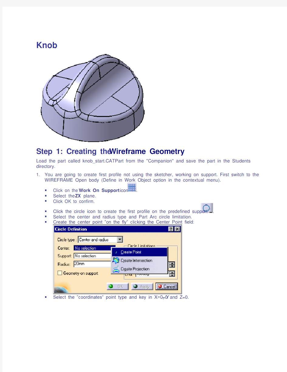
?Create the center point “on the fly” clicking the Center Point field:
?Select the “coordinates” point type and key in X=0, Y=0 and Z=0.
?Key in the radius 64mm, the start angle –90deg and the end angle 0deg:
?Click OK to confirm the first profile creation.
?Exit the Work On Support mode deleting the working support in the specification tree:
2. You are going to create second profile not using the sketcher, working on support.
?Click on the Work On Support icon.
?Select the YZ plane.
?Click OK to confirm.
?Click the circle icon to create the first profile on the predefined support .
?Select the center and radius type and Part Arc circle limitation.
?Create the center point “on the fly” clicking the Center Point field:
?Select the “coordinates” point type and key in X=30, Y=50 and Z=0.
?Key in the radius 20mm, the start angle 190deg and the end angle 260deg:
?Click OK to confirm the second profile creation.
?Delete the support in the tree.
3. You will now create the third profile using the sketcher.
?Select the Sketcher icon and select the YZ plane.
?Select the line icon and draw this line with its constraints:
?Exit the sketcher. The third profile is created.
Step 2: Creating the Basic Surfaces 1. You are going to create two extruded surfaces.
?Click on the Extrude icon .
?Select the profile 1 and key in these parameters:
?Click OK to confirm the first surface creation.
?Click on the Extrude icon .
?Select the profile 2 and key in these parameters:
?Click OK to confirm the first surface creation.
2. You are going to create the revolution surface.
?Click on the Revolution icon .
?Select the third profile and key in these parameters (axis: vertical axis of the sketch):
?Click OK to confirm. All the basic surfaces are created.
Step 3: Performing Operations the Basic Surfaces
1. You are going to trim the first extruded surface and the revolution surface.
?Click on the trim icon .
?Select the first extruded surface and the revolution surface:
?Using the “Other side element 1” and “Other side element 2” button, aim to obtain this:
?Click OK to confirm the trim creation.
2. You are going to split the second extruded surface with the previously created trim.
?Click on the split icon .
?Select the extruded surface as element to cut, and the trim as cutting element.
?Playing with the “Other side” button, aim to obtain this:
?Click OK to confirm the split creation.
3. You are going to extrapolate the previously created split surface.
?Click on the extrapolate icon .
?Select the split surface lower boundary.
?Select the split surface.
?Select the “up to element” extrapolation type.
?Select the trim surface and activate the “Assemble result” button:
?Click OK to confirm the extrapolate creation.
4. You are going to extrapolate the previously created extrapolate surface.
?Click on the extrapolate icon .
?Select the extrapolated surface higher boundary.
?Select the split surface.
?Select the “up to element” extrapolation type.
?Select the trim surface and activate the “Assemble result” button:
?Click OK to confirm the second extrapolated surface creation.
5. You are going to trim the previously created extrapolate surface with the first created trim surface.
?Click on the trim icon.
?Select the last created extrapolated surface and the first created trim.
?Using the “Other side element 1” and “Other side element 2” button, aim to obtain this:
?Click OK to confirm.
6. You are going to create a variable filet on the previously created trim.
?Click on the variable radius fillet icon .
?Select this edge and key in the radius 10mm:
?Double-click on the left radius value and key in 20mm: ?Click OK to confirm. You get this:
?Click OK to confirm the fillet creation:
7. You are going to create an edge filet on the previously created surface.
?Click on the edge fillet icon .
?Select this edge and key in the radius 5mm:
?Click OK to confirm the fillet creation:
8. You are going to create the symmetric surface and join the two surfaces.
?Click on the symmetry icon .
?Select the previously created surface as element to symmetrize and the YZ plane as reference:
?Click OK to confirm.
?Click on the join icon .
?Select the EdgeFillet.2 surface and the Symmetry.1 surface.
?Click OK to confirm the join operation.
9. You are going to create the symmetric surface from the previous join and join the two surfaces.
?Click on the symmetry icon .
?Select the previously created join as element to symmetrize and the ZX plane as reference:
?Click OK to confirm.
?Click on the join icon and select the Join.1 surface and the Symmetry.2 surface.
?Click OK to confirm the join creation.
The operations on the surfaces are all performed. You should get this:
Step 4: Analyzing and Modifying the draft angle 1. You are going to analyze the draft.
?Click on the Draft Analysis icon.
?Change to the customized view mode:
?Select the Join.2.
?Change the draft values to obtain:
?Close the draft analysis color bar.
2. Then modify the draft angle.
?Double click on the Sketch.1 in the tree: you get in the sketch.
?Modify the line inclination from 90deg into 86deg:
?Exit the sketch. The part is automatically updated:
Step 5: Offsetting a solid
1. You are going to create a solid from the previously created surface.
?Select Start / Mechanical Design / Part Design.
?Select the Join.2.
?Select the Thick Surface icon .
?Verify the Thick arrows pointing inward as shown below:
?Key in 4mm in the First Offset Value field.
?Click OK to confirm the solid creation.
?Hide the Open Body containing all the surface elements.
2. Then you are going to split the solid to make its bottom face plane.
?Change the visualization mode to Wireframe:
?Select the left view icon:
?Zoom on the left bottom to check that the bottom of the part is no more plane.
?Come back to a Shading visualization mode.
?Put the XY plane in a …?Show?? mode.
?Select the split icon.
?Select the XY plane as Splitting element.
?Click OK to confirm the split creation.
3. Now, apply a material on the thick surface:
?Select the Apply Material icon.
?Select the Rubber material under the ……other?? tab of the material library.
Drag and drop it on the knob, click on OK to confirm.