840故障代码_code
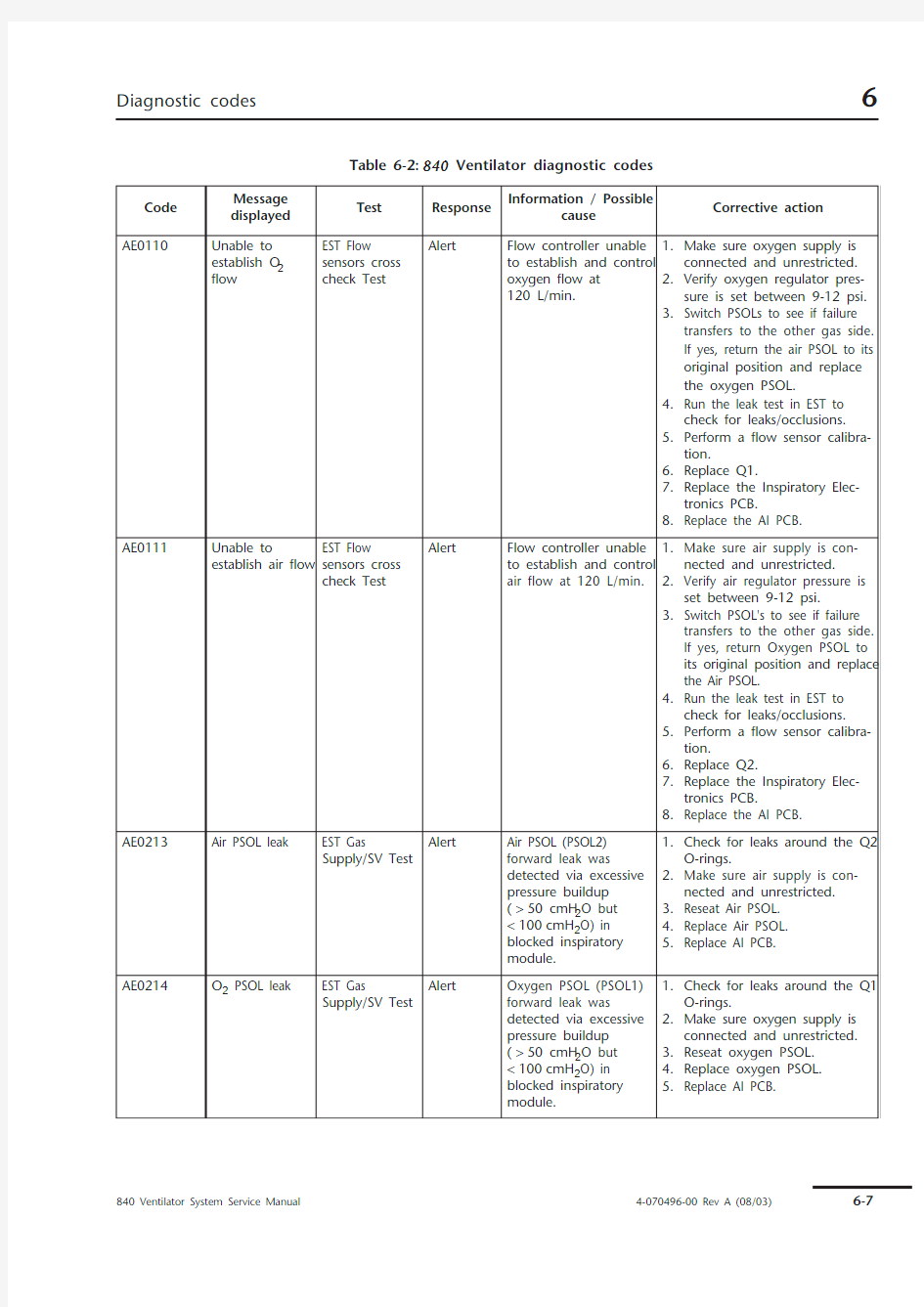

Table 6-2: 840 Ventilator diagnostic codes
Code Message
displayed
Test Response
Information / Possible
cause
Corrective action
AE0110Unable to
establish O2
flow EST Flow
sensors cross
check Test
Alert Flow controller unable
to establish and control
oxygen flow at
120 L/min.
1.Make sure oxygen supply is
connected and unrestricted.
2.Verify oxygen regulator pres-
sure is set between 9-12 psi.
3.Switch PSOLs to see if failure
transfers to the other gas side.
If yes, return the air PSOL to its
original position and replace
the oxygen PSOL.
4.Run the leak test in EST to
check for leaks/occlusions.
5.Perform a flow sensor calibra-
tion.
6.Replace Q1.
7.Replace the Inspiratory Elec-
tronics PCB.
8.Replace the AI PCB.
AE0111Unable to
establish air flow EST Flow
sensors cross
check Test
Alert Flow controller unable
to establish and control
air flow at 120 L/min.
1.Make sure air supply is con-
nected and unrestricted.
2.Verify air regulator pressure is
set between 9-12 psi.
3.Switch PSOL's to see if failure
transfers to the other gas side.
If yes, return Oxygen PSOL to
its original position and replace
the Air PSOL.
4.Run the leak test in EST to
check for leaks/occlusions.
5.Perform a flow sensor calibra-
tion.
6.Replace Q2.
7.Replace the Inspiratory Elec-
tronics PCB.
8.Replace the AI PCB.
AE0213Air PSOL leak EST Gas
Supply/SV Test Alert Air PSOL (PSOL2)
forward leak was
detected via excessive
pressure buildup
(>50 cmH2O but
<100cmH2O) in
blocked inspiratory
module.
1.Check for leaks around the Q2
O-rings.
2.Make sure air supply is con-
nected and unrestricted.
3.Reseat Air PSOL.
4.Replace Air PSOL.
5.Replace AI PCB.
AE0214O2 PSOL leak EST Gas
Supply/SV Test Alert Oxygen PSOL (PSOL1)
forward leak was
detected via excessive
pressure buildup
(>50 cmH2O but
<100cmH2O) in
blocked inspiratory
module.
1.Check for leaks around the Q1
O-rings.
2.Make sure oxygen supply is
connected and unrestricted.
3.Reseat oxygen PSOL.
4.Replace oxygen PSOL.
5.Replace AI PCB.
AE0306Test circuit not
connected EST Leak Test Alert Pressure not detected
on expiratory side
1.Make sure test circuit is prop-
erly connected.
2.Replace expiratory bacteria
filter.
3.Check for leaks around the Q3
flow sensor.
4.Check/replace the exhalation
valve.
5.Replace the expiratory pressure
transducer PCB.
AE0601GUI High Alarm
LED fails.EST GUI Lamp
Test
Alert CLEAR key pressed to
indicate LED not on.
1.Check/replace interconnect
cable between the GUI LED
PCB and the GUI CPU PCB.
2.Replace the GUI LED PCB.
AE0602GUI Medium
Alarm LED fails.EST GUI Lamp
Test
Alert CLEAR key pressed to
indicate LED not on.
1.Check/replace interconnect
cable between the GUI LED
PCB and the GUI CPU PCB.
2.Replace the GUI LED PCB.
AE0603GUI Low Alarm
LED fails.EST GUI Lamp
Test
Alert CLEAR key pressed to
indicate LED not on.
1.Check/replace interconnect
cable between the GUI LED
PCB and the GUI CPU PCB.
2.Replace the GUI LED PCB.
AE0604GUI Normal LED
fails.EST GUI Lamp
Test
Alert CLEAR key pressed to
indicate LED not on.
1.Check/replace interconnect
cable between the GUI LED
PCB and the GUI CPU PCB.
2.Replace the GUI LED PCB.
AE0605GUI Batt Backup
LED fails.EST GUI Lamp
Test
Alert CLEAR key pressed to
indicate LED not on.
1.Check/replace interconnect
cable between the GUI LED
PCB and the GUI CPU PCB
2.Replace the GUI LED PCB.
AE0606GUI On Batt Pwr
LED fails.EST GUI Lamp
Test
Alert CLEAR key pressed to
indicate LED not on.
1.Check/replace interconnect
cable between the GUI LED
PCB and the GUI CPU PCB.
2.Replace the GUI LED PCB.
AE0607G UI Compressor
Ready LED fails.EST GUI Lamp
Test
Alert CLEAR key pressed to
indicate LED not on.
1.Check/replace interconnect
cable between the GUI LED
PCB and the GUI CPU PCB.
2.Replace the GUI LED PCB.
AE0608G UI Compressor
Operating LED
fails.EST GUI Lamp
Test
Alert CLEAR key pressed to
indicate LED not on.
1.Check/replace interconnect
cable between the GUI LED
PCB and the GUI CPU PCB.
2.Replace the GUI LED PCB.
AE0609GUI 100% O2
LED fails.EST GUI Lamp
Test
Alert CLEAR key pressed to
indicate LED not on.
1.Check/replace interconnect
cable between the GUI LED
PCB and the GUI CPU PCB.
2.Replace keyboard.
AE0610GUI Alarm
Silence LED fails.EST GUI Lamp
Test
Alert CLEAR key pressed to
indicate LED not on.
1.Check/replace interconnect
cable between the GUI LED
PCB and the GUI CPU PCB.
2.Replace the GUI LED PCB.
Table 6-2: 840 Ventilator diagnostic codes (continued)
Code Message
displayed
Test Response
Information / Possible
cause
Corrective action
AE0611GUI Screen Lock
LED fails.EST GUI Lamp
Test
Alert CLEAR key pressed to
indicate LED not on.
1.Check/replace interconnect
cable between the GUI LED
PCB and the GUI CPU PCB.
2.Replace the GUI LED PCB.
AE0702Bad Vent inop
LED EST BD Lamp
Test
Alert CLEAR key pressed to
indicate one or both
ventilator inoperative
LEDs not on.
Replace BD LED PCB.
AE0703Bad SVO LED EST BD Lamp
Test Alert CLEAR key pressed to
indicate one or both
SVO LEDs not on.
Replace BDU LED PCB.
AE0704Bad Loss of GUI
LED EST BD Lamp
Test
Alert CLEAR key pressed to
indicate loss of GUI LED
not on.
Replace BDU LED PCB.
AE1001Air PSOL
loopback
current OOR EST PSOL
Loopback Test
Alert Air PSOL (PSOL2)
loopback current out of
range of drive current.
1.Verify that the air supply is
good.
2.Verify air regulator pressure set
to between 9 and 12 psi.
3.Switch PSOLs to see if failure
transfers to the other gas side.
If yes, return oxygen PSOL
(PSOL1) to its original position
and replace PSOL2.
4.Switch Q1 and Q2, run a flow
sensor calibration and rerun
test. If the problem transfers to
the other gas side, return Q1 to
its original position and replace
Q2.
5.Replace the AI PCB.
6.Replace the Inspiratory
Electronics PCB.
AE1002O2 PSOL
loopback
current OOR
EST PSOL
Loopback Test
Alert Oxygen PSOL (PSOL1)
loopback current out of
range of drive current.
1.Verify that the oxygen supply is
good.
2.Verify oxygen regulator pres-
sure set to between 9 and 12
psi.
3.Switch PSOLs to see if failure
transfers to the other gas side.
If yes, return the air PSOL to its
original position and replace
PSOL1.
4.Switch Q1 and Q2, run a flow
sensor calibration and rerun
test. If the problem transfers to
the other gas side, return Q2 to
its original position and replace
Q1.
5.Replace the AI PCB.
6.Replace the Inspiratory
Electronics PCB.
Table 6-2: 840 Ventilator diagnostic codes (continued)
Code Message
displayed
Test Response
Information / Possible
cause
Corrective action
AE1104Insp check valve
test failed EST Safety
System Test
Alert It took too little time to
relieve excess pressure
through open safety
valve, indicating
inspiratory check valve
(CV3) may be damaged
or incorrectly mounted.
1.Make sure test circuit is con-
nected.
2.Make sure CV3 is not installed
backward.
3.Replace CV3.
AE1201Exp valve
loopback
current OOR EST Exp Valve
Loopback Test
Alert Exhalation valve
loopback current is out
of range of drive
current.
1.Verify that the system has no
leaks or occlusions by running
the leak test in EST.
2.Clean exhalation valve
diaphragm.
3.Calibrate the exhalation valve.
4.Clean/replace the exhalation
valve.
5.Replace the AI PCB.
AE1305Seal test failed EST Exp Valve
Seal Test Alert Seal test Δ pressure is
above alert level but
below failure level.
1.Verify that the system has no
leaks or occlusions by running
the leak test in EST.
2.Clean the exhalation valve.
3.Calibrate exhalation valve.
4.Replace the exhalation valve.
5.Replace the AI PCB.
AE1600Compressor
Test - Not
installed EST
Compressor
Test
Status Ventilator did not sense
a compressor attached
and skipped test.
No action required.
AE1601Wall air pressure
detected EST
Compressor
Test
Alert Wall air pressure switch
(PS2) detected air after
user was prompted to
disconnect air.
1.Make sure air supply is discon-
nected.
2.Disconnect PS2 and rerun test.
If test passes, replace PS2.
AE1602ac power not
connected EST
Compressor
Test
Alert System is still running
on battery power after
prompting user to
connect ac power.
Compressor can only
run on ac (facility)
power.
1.Plug in ventilator power cord
and check the cord connec-
tion at the ventilator.
2.Check ac.
3.Disconnect BPS to isolate prob-
lem.
4.Replace power supply.
AE1603Compressor
pressure not
detected
EST
Compressor
Test
Alert Compressor pressure
transducer (PC)
indicates that
compressor air is not
present, although
compressor motor is
on.
1.Run compressor leak test to
check for leaks.
https://www.wendangku.net/doc/aa2844694.html,e leak detector to check
for leaks at the accumulator
fittings and other tubing
connections.
b.Verify no leaks at CV2 within
the ventilator by plugging
the air inlet fitting.
2.Replace compressor PCB.
3.Contact Puritan-Bennett Tech-
nical Support.
Table 6-2: 840 Ventilator diagnostic codes (continued)
Code Message
displayed
Test Response
Information / Possible
cause
Corrective action
AE1604Run mode time
OOR EST
Compressor
Test
Alert Compressor timer is not
running while
compressor motor is
on.
Listen for motor. If motor is on,
replace compressor PCB.
Otherwise, replace compressor.
AE1606Compressor
pressure
detected EST
Compressor
Test
Alert Compressor pressure
transducer (PC)
indicates that
compressor air is
present after
compressor motor is
disabled and
accumulator drained.
Replace compressor PCB.
AE1607Disabled mode
time OOR EST
Compressor
Test
Alert Compressor timer is
running while
compressor motor is
off.
Replace compressor PCB.
AE1608Unable to test
standby mode EST
Compressor
Test
Alert Compressor standby
mode check cannot be
run, because of inability
to verify timer
functionality during
compressor run and
disabled tests.
1.Troubleshoot code AE1604 or
AE1607, if present.
2.Replace compressor PCB.
AE1609Standby mode
time OOR EST
Compressor
Test
Alert Compressor motor is
still running. During
standby mode test
phase, compressor
motor should
eventually turn off.
Replace compressor PCB.
AE1610Unable to
perform
compressor load
test EST
Compressor
Test
Alert Compressor load test
cannot be run, because
of inability to verify PC
during compressor run
and disabled tests.
Troubleshoot code AE1603 or
AE1606.
AE1611Compressor
load test failed EST
Compressor
Test
Alert Compressor unable to
maintain minimum
pressure under worst-
case breath delivery
waveform.
1.Run compressor leak test to
check for compressor leak.
https://www.wendangku.net/doc/aa2844694.html,e leak detector to check
for leaks at the accumulator
fittings and other tubing
connections.
b.Verify no leaks at CV2 within
the ventilator by plugging
the air inlet fitting.
2.Replace compressor.
3.Replace compressor PCB.
AE1700Compressor
Leak Test - Not
installed
EST
Compressor
Leak Test
Status Ventilator did not sense
a compressor attached
and skipped test.
No action required. Table 6-2: 840 Ventilator diagnostic codes (continued)
Code Message
displayed
Test Response
Information / Possible
cause
Corrective action
AE1701Unable to
perform
compressor leak
test EST
Compressor
Leak Test
Alert Compressor leak test
cannot be run, because
of inability to verify
timer functionality.
1.Troubleshoot accompanying
code AE1604 or AE1607.
2.Replace compressor PCB.
AE1702Wall air pressure
detected EST
Compressor
Leak Test
Alert Wall air pressure switch
(PS2) detected air
presence after user was
prompted to
disconnect air.
1.Make sure air supply is discon-
nected.
2.Disconnect PS2 and rerun test.
If test passes, replace PS2.
AE1703Wall air pressure
not detected EST
Compressor
Leak Test
Alert Wall air pressure switch
(PS2) did not detect air
presence after user was
prompted to connect
air.
1.Make sure air supply is con-
nected.
2.Run Gas Supply/SV Test.
AE1704Compressor
leak detected EST
Compressor
Leak Test
Alert Compressor leak was
detected using
compressor timer to
detect compressor
turning on momentarily
during test.
Troubleshoot compressor
compartment or inspiratory
module for leaks.
AE1901GUI touch: Error EST GUI Touch
Test Alert Touch screen error
occurred (e.g., blocked
beam or low-level
error), buffer cannot be
read, or report is
invalid.
1.Clean touch screen, removing
any obstructions.
2.Replace touch frame PCB.
3.Replace GUI CPU PCB.
AE2001Bad GUI serial
port EST GUI Serial
Port Test
Alert While in loopback
mode, failed to verify
received message was
identical to transmitted
message.
Replace GUI CPU PCB.
AE2101Battery not
charged EST Battery
Test
Alert BPS not fully charged at
start of test.
1.Allow BPS to fully charge, then
repeat test.
2.Replace BPS PCB.
3.Replace battery pack.
4.Replace BD CPU PCB.
AE2102Battery not
discharging
EST Battery
Test
Alert BPS not discharging
after ac power was
disconnected.
1.Verify ac power is disconnected
when prompted.
2.Replace BPS PCB.
3.Replace battery pack.
4.Replace BD CPU PCB.
Table 6-2: 840 Ventilator diagnostic codes (continued)
Code Message
displayed
Test Response
Information / Possible
cause
Corrective action
AE2103Bad Backup
Power Supply EST Battery
Test
Alert While BPS was
discharging, BPS
voltage dropped below
accepted level or
dropped too quickly.
1.Ensure that the battery pack is
fully charged by checking that
the green LED on the BPS is lit
prior to initiating an EST. If the
amber LED is lit, allow the unit
to charge the batteries prior to
rerunning EST.
2.Replace the battery pack.
3.Replace the BPS PCB.
4.Replace the AI PCB.
5.Replace the power supply.
AE2104Battery not
charging EST Battery
Test
Alert BPS not charging after
ac power was
reconnected.
1.Verify that ac power is recon-
nected when prompted and
that ac is good.
2.Replace BPS PCB.
3.Replace the battery pack.
4.Replace the power supply.
5.Replace the BD CPU.
6.Replace the AI PCB.
AE2300GUI Nurse Call
Test - Not
installed
EST Test Status User pressed CLEAR to
indicate nurse’s call
device not installed.
Test was skipped.
No action required. Table 6-2: 840 Ventilator diagnostic codes (continued)
Code Message
displayed
Test Response
Information / Possible
cause
Corrective action
AS0010Unable to
establish O2
flow
SST flow sensor
test
Alert Flow controller unable
to establish and control
oxygen flow at
120 L/min.
1.Make sure oxygen supply is
connected and unrestricted.
2.Verify that the oxygen supply
meets minimum pressure
requirements.
3.Verify that the patient circuit
system has no leaks or occlu-
sions. If not sure, run the first
four tests in EST to get to the
leak test. If the leak test passes
in EST, exit out of EST. Correct
the leak or occlusion in the
patient circuit used in SST and
rerun or try another patient cir-
cuit.
4.Check the oxygen inlet filter
assembly.
5.Verify that the oxygen regula-
tor pressure is set between 9-
12 psi.
6.Run a flow sensor calibration.
7.Switch Q1 and Q2. Rerun the
flow sensor calibration and
EST. If the failure transfers to
the air side, return Q2 back to
its original position and replace
Q1.
8.Switch PSOLs to see if the fail-
ure transfers to the air side. If
yes, return PSOL2 back to its
original position and replace
PSOL1.
Table 6-2: 840 Ventilator diagnostic codes (continued)
Code Message
displayed
Test Response
Information / Possible
cause
Corrective action
AS0011Unable to
establish air flow SST flow sensor
test
Alert 1.Flow controller
unable to establish
and control air flow
at 120 L/min.
1.Make sure air supply is con-
nected and unrestricted.
2.Verify that the air supply meets
minimum pressure require-
ments.
3.Verify that the patient circuit
system has no leaks or occlu-
sions. If not sure, run the first
four tests in EST to get to the
leak test. If the leak test passes
in EST, exit out of EST. Correct
the leak or occlusion in the
patient circuit used in SST and
rerun or try another patient cir-
cuit.
4.Check the air inlet filter (F2).
5.Verify that the air regulator
pressure is set between 9-12
psi.
6.Run a flow sensor calibration.
7.Switch Q1 and Q2. Rerun the
flow sensor calibration and
EST. If the failure transfers to
the oxygen side, return Q1
back to its original position and
replace Q2.
8.Switch PSOLs to see if the fail-
ure transfers to the oxygen
side. If yes, return PSOL1 back
to its original position and
replace PSOL2.
AS0012O2 pressure not
detected SST flow sensor
test
Alert Oxygen pressure not
detected via PS1. Only
air available for SST.
Make sure oxygen supply is
connected.
AS0013Wall air pressure
not detected SST flow sensor
test
Alert Air pressure not
detected via PS2 or PC.
Only oxygen available
for SST.
Make sure air supply is connected.
AS0202Excessive leak SST Circuit leak Alert Pressure drops to 85
cmH2O in 10 s,
then in 10 s more by
≥ 10 cmH2O.1.Make sure patient circuit is
connected and is not leaking.
2.Check exhalation valve opera-
tion.
3.Verify connections of bacteria
filters and humidifier are
secure.
AS0305Occluded
expiratory filter SST Expiratory
filter
Alert Pressure drop across
filter > 2cmH2O, but
<3 cmH2O.
Consider replacing expiratory
filter.
AS0308Occluded
expiratory
compartment
SST Expiratory
filter
Alert Exhalation
compartment pressure
>3 cmH2O but
< 4cmH2O.
1.Check compartment for
obstruction.
2.Verify exhalation valve opera-
tion by running EST.
Table 6-2: 840 Ventilator diagnostic codes (continued)
Code Message
displayed
Test Response
Information / Possible
cause
Corrective action
AS0311Low expiratory
filter ΔP SST Expiratory
filter
Alert Pressure drop
across expiratory filter
< 0.4 cmH2O, but
> 0.1 cmH2O.
1.Repeat test, following direc-
tions more closely.
2.Replace filter.
AS0403Occluded
inspiratory limb SST Circuit
Resistance
Alert Inspiratory limb
pressure > 8.5 cmH2O
(adult) or 5.5cmH2O
(pediatric), but
< 12.5 cmH2O (adult)
or 7.5cmH2O
(pediatric), indicating
occlusion.
Check for occluded patient tubing.
AS0406Occluded
exhalation limb SST Circuit
Resistance
Alert Expiratory limb
pressure > 8.5cmH2O
(adult) or 5.5cmH2O
(pediatric) but > 12.5
cmH2O (adult) or
7.5cmH2O (pediatric),
indicating occlusion.
Check for occluded patient tubing.
AS0407Unable to reach
min peak flow SST Circuit
Resistance
Alert During characterization
of total circuit
resistance over a range
of flows, peak flow
< 80L/min but > 60 L/
min.
Check for kinked or occluded
patient tubing.
AS0411Unable to reach
min peak flow SST Circuit
Resistance
Alert During characterization
of total circuit
resistance over a range
of flows, peak flow was
less than alert
threshold.
Check for kinked or occluded
patient tubing.
AS0413Insp limb
resistance low SST Circuit
Resistance
Alert Inspiratory limb
pressure < 0.6 cmH2O
(adult) or 5.5cmH2O
(pediatric), but
> 0.2 cmH2O.
1.Make sure inspiratory filter is
installed.
2.Repeat test, following direc-
tions more closely.
3.Replace inspiratory filter.
4.Replace patient circuit.
AS0414Exp limb
resistance low SST Circuit
Resistance
Alert Expiratory limb
pressure < 0.6cmH2O
(adult) or 0.5 cmH2O
(pediatric), but
> 0.2cmH2O.
Replace patient circuit.
AS0505Excessive
compliance
SST
Compliance
calibration
Alert High compliance
>6 mL/cmH2O (adult)
or 4.5mL/cmH2O
(pediatric), but
< 12mL/cmH2O (adult)
or 9 mL/cmH2O
(pediatric).
1.Make sure correct patient tub-
ing type was specified in SST.
2.Replace patient circuit. Table 6-2: 840 Ventilator diagnostic codes (continued)
Code Message
displayed
Test Response
Information / Possible
cause
Corrective action
AS0507Compliance low SST
Compliance
calibration Alert High compliance falls
below 1.56 mL/cmH2O
(adult) or 1.34 mL/
cmH2O (pediatric) but
not lower than
1.05 mL/cmH2O.
1.Make sure correct patient tub-
ing type was specified in SST.
2.Replace patient circuit with a
known good circuit and filter
set.
3.Run EST to check the operation
of PI and PE during the Circuit
Pressure Test. Replace applica-
ble pressure transducer.
4.Run Atmospheric Pressure
Transducer calibration.
AS0509Excessive
compliance SST
Compliance
calibration
Alert Low compliance >
6 mL/cmH2O (adult) or
4.5mL/cmH2O
(pediatric), but <
12mL/cmH2O (adult)
or 9 mL/cmH2O
(pediatric).
1.Make sure correct patient tub-
ing type was specified in SST.
2.Replace patient circuit with a
known good circuit and filter
set.
3.Run EST to check the operation
of PI and PE during the Circuit
Pressure Test. Replace applica-
ble pressure transducer.
4.Run Atmospheric Pressure
Transducer calibration.
AS0511Compliance low SST
Compliance
calibration Alert Low compliance falls
below 1.56 mL/cmH2O
(adult) or 1.34 mL/
cmH2O (pediatric), but
not below
1.05 mL/cmH2O.
1.Make sure correct patient tub-
ing type was specified in SST.
2.Replace patient circuit with a
known good circuit and filter
set.
3.Run EST to check the operation
of PI and PE during the Circuit
Pressure Test. Replace applica-
ble pressure transducer.
4.Run Atmospheric Pressure
Transducer calibration.
Dxxxxx Assertion Background
Checks (BD)Failure that
results in a
POST or a
reset
System generated a
reset to correct a
boundary check or
possible data
corruption of control
variables.
Replace the BDCPU PCB.
DT0002Bus error /
Access fault Background
Checks (BD)
Failure that
results in a
POST or a
reset
Hardware trap from an
access fault due to a
bad memory chip, bad
control line, or a
hardware timing issue.
Replace the BD CPU PCB.
Exxxxx Varies Background
Checks (GUI)Status A status message
indicating an event that
was intentionally
caused.
Table 6-2: 840 Ventilator diagnostic codes (continued)
Code Message
displayed
Test Response
Information / Possible
cause
Corrective action
NOTE:
For all "FE" codes (failures reported during EST), diagnose the problem and perform the repair.
Run a complete EST to reset the EST test failure in memory. If there is a failed EST test result in
memory, normal operation is prevented until the failed EST test is rerun and passes.
FE0001Inspiratory
autozero out of
range EST Circuit
Pressure Test
Failure Inspiratory pressure
transducer ADC count
at 0cmH2O is out of
range.
1.Replace SOL1.
2.Replace Inspiratory Electronics
PCB.
3.Replace AI PCB.
FE0002Expiratory
autozero out of
range EST Circuit
Pressure Test
Failure Exhalation pressure
sensor ADC count at
0cmH2O is out of
range.
1.Replace SOL
2.
2.Replace exhalation transducer
PCB.
3.Replace AI PCB.
FE0003Failed to reach
test pressure EST Circuit
Pressure Test
Failure Unable to build
pressure (air) to
10cmH2O at
5 L/min within time-out
period.
1.Make sure that test circuit is
installed and air supply or com-
pressor is available and good.
2.Verify that the air regulator
pressure is set between 9-12
psi.
3.Verify that the patient circuit
system has no leaks or occlu-
sions by running the first four
tests in EST to get to the leak
test.
FE0004Cross-check
failed EST Circuit
Pressure Test
Failure Inspiratory/expiratory
pressure transducer
readings at 10cmH2O
test pressure are too far
apart.
1.Verify that the system has no
leaks or occlusions. If not sure,
run the first four tests in EST to
run the leak test
2.If the leak test passes in EST,
exit out of EST. Review the
data for the Circuit Pressure
Test to determine which pres-
sure transducer is out of range:
PI or PE. Replace applicable
pressure transducer.
3.Replace AI PCB.
FE0005Bad insp
autozero
solenoid EST Circuit
Pressure Test
Failure Inspiratory pressure
reading (taken after
inspiratory pressure
transducer autozero
solenoid (SOL1)
actuated) out of range
(-0.60 to 0.60 cmH2O).
1.Replace SOL1.
2.Replace Inspiratory Electronics
PCB.
3.Replace AI PCB.
FE0006Bad exp
autozero sol
EST Circuit
Pressure Test
Failure Expiratory pressure
reading (taken after
expiratory pressure
transducer autozero
solenoid (SOL2)
actuated) out of range
(-0.60 to 0.60 cmH2O).
1.Replace SOL
2.
2.Replace exhalation transducer
PCB.
3.Replace AI PCB.
Table 6-2: 840 Ventilator diagnostic codes (continued)
Code Message
displayed
Test Response
Information / Possible
cause
Corrective action
FE0007Cross-check
failed EST Circuit
Pressure Test
Failure Inspiratory/expiratory
pressure transducer
measurements at 50 or
100cmH2O test
pressure are too far
apart.
1.Replace the expiratory bacteria
filter.
2.Verify that the system has no
leaks or occlusions. If not sure,
run the first four tests in EST to
run the leak test.
3.If the leak test passes in EST,
exit out of EST. Review the data
for the Circuit Pressure Test to
determine which pressure
transducer is out of range: PI or
PE. Replace applicable pres-
sure transducer.
4.Replace AI PCB.
FE0008Failed to reach
test pressure EST Circuit
Pressure Test
Failure Unable to build
pressure (air) to 50 or
100 cmH2O at 5 L/min
within time-out period.
1.Make sure air supply or com-
pressor is available.
2.Check for system leak at the
expiratory bacteria filter or O2
sensor. If not sure, run the first
four tests in EST to run the leak
test.
FE0010ac power not
connected EST Circuit
Pressure Test
Failure System is still running
on battery power after
prompting user to
connect ac power. EST
can only run on ac
(facility) power.
1.Plug in ventilator power cord.
2.Disconnect BPS to isolate prob-
lem.
3.Replace power supply.
FE0101O2 flow sensor
cross check
failed
EST Flow
sensors cross
check Test
Failure Oxygen flow sensor
(Q1) cross-check failed.
1.Make sure oxygen supply is
connected and unrestricted.
2.Verify that the oxygen supply is
good.
3.Verify that the system has no
leaks or occlusions. If not sure,
run the first four tests in EST to
run the leak test.
4.Run a flow sensor calibration.6.
Switch Q1 and Q2. Rerun the
flow sensor calibration and
EST. If the failure transfers to
the air side, return Q2 back to
its original position and replace
Q1.
5.Switch PSOLs to see if the fail-
ure transfers to the air side. If
yes, return PSOL2 back to its
original position and replace
PSOL1.
6.Replace exhalation flow sensor
(Q3)
7.Replace AI PCB.
Table 6-2: 840 Ventilator diagnostic codes (continued)
Code Message
displayed
Test Response
Information / Possible
cause
Corrective action
FE0102O2 PSOL current
out of range EST Flow
sensors cross
check Test
Failure Oxygen PSOL (PSOL1)
current is out of range
with respect to flow
sensor (Q1).
1.Make sure oxygen supply is
connected and unrestricted.
2.Verify that the oxygen supply is
good.
3.Verify that the system has no
leaks or occlusions. If not sure,
run the first four tests in EST to
run the leak test.
4.Switch PSOLs to see if the fail-
ure transfers to the air side. If
yes, return PSOL2 back to its
original position and replace
PSOL1.
5.Run a flow sensor calibration.
6.Switch Q1 and Q2. Rerun the
flow sensor calibration and
EST. If the failure transfers to
the air side, return Q2 back to
its original position and replace
Q1.
FE0103Air flow sensor
cross check
failed
EST Flow
sensors cross
check Test
Failure Inspiratory module air
flow sensor (Q2) cross-
check failed.
1.Make sure air supply is con-
nected and unrestricted.
2.Verify that the air supply is
good.
3.Verify that the system has no
leaks or occlusions. If not sure,
run the first four tests in EST to
run the leak test.
4.Run a flow sensor calibration.
5.Switch Q1 and Q2. Rerun the
flow sensor calibration and
EST. If the failure transfers to
the oxygen side, return Q1
back to its original position and
replace Q2.
6.Switch PSOLs to see if the fail-
ure transfers to the air side. If
yes, return PSOL back to its
original position and replace
PSOL2
7.Replace exhalation flow sensor
(Q3).
8.Replace AI PCB.
Table 6-2: 840 Ventilator diagnostic codes (continued)
Code Message
displayed
Test Response
Information / Possible
cause
Corrective action
FE0104Air PSOL current
out of range EST Flow
sensors cross
check Test
Failure Air PSOL (PSOL2)
current is out of range
with respect to air flow
sensor (Q2).
1.Make sure air supply is con-
nected and unrestricted.
2.Verify that the air supply is
good.
3.Verify that the system has no
leaks or occlusions. If not sure,
run the first four tests in EST to
run the leak test.
4.Switch PSOLs to see if the fail-
ure transfers to the air side. If
yes, return PSOL back to its
original position and replace
PSOL2
5.Run a flow sensor calibration.
6.Switch Q1 and Q2. Rerun the
flow sensor calibration and
EST. If the failure transfers to
the oxygen side, return Q1
back to its original position and
replace Q2.
FE0106Unable to
establish O2
flow EST Flow
sensors cross
check Test
Failure Flow controller unable
to establish and control
oxygen flow at 60, 5,
and 1 L/min.
1.Make sure oxygen supply is
connected.
2.Check regulated oxygen pres-
sure.
3.Replace PSOL1 or Q1.
4.Replace AI PCB.
FE0107Unable to
establish air flow EST Flow
sensors cross
check Test
Failure Flow controller unable
to establish and control
air flow at 60, 5, and 1
L/min.
1.Make sure air supply is con-
nected.
2.Check regulated air pressure.
3.Perform flow sensor calibra-
tion.
4.Replace PSOL2 or Q2.
5.Replace AI PCB.
FE0108O2 zero flow
check failed EST Flow
sensors cross
check Test
Failure Inspiratory flow >
0.153 L/min with
oxygen PSOL (PSOL1)
commanded to 0
(closed).
1.Verify no leaks at the Q1
O-rings.
2.Run EST Gas Supply Test to
check for PSOL1 leak. Remove
and then reseat PSOL1
3.Replace PSOL1.
4.Perform a flow sensor calibra-
tion.
5.Replace Q1.
FE0109Air zero flow
check failed
EST Flow
sensors cross
check Test
Failure Inspiratory flow >0.153
L/min with air PSOL
(PSOL2) commanded
to 0 (closed).
1.Verify no leaks at the Q2
O-rings.
2.Run EST Gas Supply Test to
check for PSOL2 leak. Remove
and then reseat PSOL2
3.Replace PSOL2.
4.Perform a flow sensor calibra-
tion.
5.Replace Q2.
Table 6-2: 840 Ventilator diagnostic codes (continued)
Code Message
displayed
Test Response
Information / Possible
cause
Corrective action
FE0204Wall air pressure
not detected EST Gas
Supply/SV Test
Failure Wall air not detected
initially and wall air still
not detected after user
was prompted to
connect wall air.
1.Make sure air supply is con-
nected.
2.Check PS2: Remove the wiring
connectors from PS2 and
jumper the connectors to each
other. If the system now rec-
ognizes the air supply, replace
PS2.
FE0205O2 pressure not
detected EST Gas
Supply/SV Test
Failure Oxygen pressure not
detected initially and
oxygen pressure still
not detected after user
was prompted to
connect oxygen.
1.Make sure oxygen supply is
connected.
2.Check PS1: Remove the wiring
connectors from PS1 and
jumper the connectors to each
other. If the system now rec-
ognizes the air supply, replace
PS1.
FE0206O2 pressure
detected (O2
not
disconnected)EST Gas
Supply/SV Test
Failure Oxygen pressure switch
detected presence of
oxygen after user was
prompted to
disconnect oxygen.
1.Make sure oxygen supply is dis-
connected.
2.Replace Inspiratory Electronics
PCB.
3.Replace PS1.
FE0207Air PSOL leak EST Gas
Supply/SV Test Failure Air PSOL (PSOL2)
forward leak was
detected via excessive
pressure buildup (>100
cmH2O) in blocked
inspiratory module.
1.Check for leaks around the Q2
O-rings.
2.Verify that the safety valve
relieves pressures above 100
cmH2O. Listen for the pressure
relief while watching the
numeric digital display of sys-
tem pressure in the upper
screen. If the safety valve does
not crack open, replace the
safety valve.
3.Replace PSOL2.
FE0208Wall air pressure
detected EST Gas
Supply/SV Test
Failure Wall air pressure switch
(PS2) detected wall air
after user was
prompted to
disconnect it.
1.Make sure air supply is discon-
nected.
2.Replace Inspiratory Electronics
PCB.
3.Replace PS2.
FE0209O2 PSOL leak EST Gas
Supply/SV Test Failure Oxygen PSOL (PSOL1)
forward leak was
detected via excessive
pressure buildup (>100
cmH2O) in blocked
inspiratory module.
1.Check for leaks around the Q1
O-rings.
2.Verify that the safety valve
relieves pressures above 100
cmH2O. Listen for the pressure
relief while watching the
numeric digital display of sys-
tem pressure in the upper
screen. If the safety valve does
not crack open, replace the
safety valve.
3.Replace PSOL1.
Table 6-2: 840 Ventilator diagnostic codes (continued)
Code Message
displayed
Test Response
Information / Possible
cause
Corrective action
FE0210SV pressure
relief failed EST Gas
Supply/SV Test
Failure Safety valve cracking
pressure and/or peak
steady-state pressure is
out of range.
1.Make sure To patient port is
blocked.
2.Check for leaks at the O2 sen-
sor, SOL1 or PI.
3.Replace the safety valve.
4.Replace PI.
FE0211O2 pressure not
detected EST Gas
Supply/SV Test
Failure PS1 did not detect
oxygen after user was
prompted to connect it.
1.Make sure oxygen supply is
connected.
2.Replace Inspiratory Electronics
PCB.
FE0212Compressor
pressure
detected EST Gas
Supply/SV Test
Failure Compressor pressure
transducer (PC)
detected that
compressor was
pressurized.
Replace compressor PCB.
FE0215Air zero flow
check failed EST Gas
Supply/SV Test
Failure During zero-flow check,
air flow sensor (Q2)
reads >0.05 L/min.
1.Make sure gas supplies are dis-
connected.
2.Make sure compressor is not
running.
3.Verify no leaks at the Q2
O-rings.
4.Check for PSOL2 leak.
5.Remove and then reseat
PSOL2.
6.Perform a flow sensor calibra-
tion.
7.Replace PSOL2.
8.Replace Q2.
FE0216O2 zero flow
check failed EST Gas
Supply/SV Test
Failure During zero-flow check,
oxygen flow sensor
(Q1) reads >0.05 L/
min.
1.Make sure gas supplies are dis-
connected.
2.Make sure compressor is not
running.
3.Verify no leaks at the Q2
O-rings.
4.Check for PSOL2 leak.
5.Remove and then reseat
PSOL2.
6.Perform a flow sensor calibra-
tion.
7.Replace PSOL2.
8.Replace Q2.
FE0217Exp zero flow
check failed
EST Gas
Supply/SV Test
Failure During zero-flow check,
exhalation flow sensor
(Q3) reads >0.1 L/min.
1.Make sure gas supplies are dis-
connected.
2.Make sure compressor is not
running.
3.Verify no leaks at the Q3
O-rings.
4.Perform a flow sensor calibra-
tion.
5.Replace Q3.
Table 6-2: 840 Ventilator diagnostic codes (continued)
Code Message
displayed
Test Response
Information / Possible
cause
Corrective action
FE0301Excessive leak EST Leak Test Failure System pressure
dropped below failure
pressure level.1.Make sure test circuit is con-
nected and is not leaking.
2.Check for system leaks or
occlusions especially at the O2
sensor and expiratory filter. 3.Verify secure connection of
expiratory filter.
4.Check exhalation valve opera-
tion.
FE0305Unable to
establish
pressure EST Leak Test Failure System cannot attain
leak test starting
pressure using oxygen
or air within time-out
period.
1.Make sure test circuit is con-
nected and is not leaking.
2.Check exhalation valve opera-
tion, and verify secure connec-
tion of expiratory filter.
FE0401Accept key fails.EST GUI
Keyboard Test Failure Wrong key pressed or
key not pressed within
15 s.
1.Repeat test.
2.Replace keyboard.
FE0402Clear key fails.EST GUI
Keyboard Test Failure Wrong key pressed or
key not pressed within
15 s.
1.Repeat test.
2.Replace keyboard.
FE0403Insp. Pause key
fails.EST GUI
Keyboard Test
Failure Wrong key pressed or
key not pressed within
15 s.
1.Repeat test.
2.Replace keyboard.
FE0404Exp. Pause key
fails.EST GUI
Keyboard Test
Failure Wrong key pressed or
key not pressed within
15 s.
1.Repeat test.
2.Replace keyboard.
FE0405Man Insp fails.EST GUI
Keyboard Test Failure Wrong key pressed or
key not pressed within
15 s.
1.Repeat test.
2.Replace keyboard.
FE0406100% O2/CAL
key fails.EST GUI
Keyboard Test
Failure Wrong key pressed or
key not pressed within
15 s.
1.Repeat test.
2.Replace keyboard.
FE0407Info key fails.EST GUI
Keyboard Test Failure Wrong key pressed or
key not pressed within
15 s.
1.Repeat test.
2.Replace keyboard.
FE0408Alarm Reset key
fails.EST GUI
Keyboard Test
Failure Wrong key pressed or
key not pressed within
15 s.
1.Repeat test.
2.Replace keyboard.
FE0409Alarm Silence
key fails.EST GUI
Keyboard Test
Failure Wrong key pressed or
key not pressed within
15 s.
1.Repeat test.
2.Replace keyboard.
FE0410Alarm Volume
key fails.EST GUI
Keyboard Test
Failure Wrong key pressed or
key not pressed within
15 s.
1.Repeat test.
2.Replace keyboard.
FE0411Screen
brightness fails.
EST GUI
Keyboard Test
Failure Wrong key pressed or
key not pressed within
15 s.
1.Repeat test.
2.Replace keyboard. Table 6-2: 840 Ventilator diagnostic codes (continued)
Code Message
displayed
Test Response
Information / Possible
cause
Corrective action
FE0412Screen contrast
key fails.EST GUI
Keyboard Test
Failure Wrong key pressed or
key not pressed within
15 s.
1.Repeat test.
2.Replace keyboard.
FE0413Screen lock key
fails.EST GUI
Keyboard Test
Failure Wrong key pressed or
key not pressed within
15 s.
1.Repeat test.
2.Replace keyboard.
FE0501Bad knob EST GUI Knob
Test Failure Knob was not turned in
direction as prompted
within 15 s.
1.Repeat test.
2.Replace keyboard.
FE0801SAAS
(Safety Audible
Alarm System)
test failed EST GUI Audio
Test
Failure CLEAR key pressed to
indicate GUI audio
diagnostic failed.
1.Verify the GUI alarm cable con-
nection to the GUI CPU PCB.
2.Replace GUI alarm assembly.
3.Replace GUI CPU PCB.
FE0901Bad alarm cable EST BDU Audio
Test Failure Alarm cable voltage is
out of range (<3.5 or
>5.05 V).
1.Make sure BD alarm cable is
connected.
2.Replace BD alarm.
3.Replace AI PCB.
4.Replace BD alarm cable.
FE0902Bad power fail
cap EST BDU Audio
Test
Failure Power failure capacitor
initial voltage is out of
range (<4.5 or >5.05
V).
1.Make sure BD alarm cable is
connected.
2.Replace BD alarm.
3.Replace AI PCB.
4.Replace BD alarm cable.
5.Replace Motherboard PCB.
FE0903Bad power fail
cap EST BDU Audio
Test
Failure Power failure capacitor
final voltage is out of
range or RC constant
<60 s.
1.Make sure BD alarm cable is
connected.
2.Replace BD alarm.
3.Replace AI PCB.
FE0904Bad BD audio EST BDU Audio
Test Failure CLEAR key pressed to
indicate user did not
hear alarm, although
alarm was active.
1.Make sure BD alarm cable is
connected.
2.Replace BD alarm.
3.Replace AI PCB.
4.Replace BD alarm cable.
FE1101Safety valve
occluded EST Safety
System Test
Failure Excessive safety valve
back pressure when
safety valve is open.
Replace safety valve.
FE1102Bad safety valve
driver or
loopback EST Safety
System Test
Failure Safety valve loopback
current is out of range
during one or more of
timed test points.
1.Replace safety valve.
2.Replace AI PCB.
3.Replace Inspiratory Electronics
PCB.
FE1103Insp check valve
test failed EST Safety
System Test
Failure It took too long to
relieve excess pressure
through open safety
valve, indicating
inspiratory check valve
(CV3) is occluded or
test circuit is too large.
1.Make sure proper test circuit is
used.
2.Make sure CV3 is not installed
backward.
3.Replace CV3.
4.Replace Safety Valve (SV).
Table 6-2: 840 Ventilator diagnostic codes (continued)
Code Message
displayed
Test Response
Information / Possible
cause
Corrective action
FE1105Unable to
establish flow EST Safety
System Test
Failure Flow controller unable
to establish and control
gas flow at 60 L/min.
1.Make sure air supply is con-
nected and unrestricted.
2.Check air regulator pressure.
3.Run flow sensor calibration.
4.Switch PSOLs to see if test
passes. If it does, return PSOL1
to its original position and
replace PSOL2.
5.Replace Q2.
FE1301Seal test failed EST Exp Valve
Seal Test Failure Seal test Δ pressure is
above failure level.
1.Clean exhalation valve.
2.Calibrate exhalation valve.
3.Run flow sensor calibration.
4.Replace exhalation valve.
5.Replace AI PCB.
6.Replace PE.
FE1302Exp valve temp
OOR EST Exp Valve
Seal Test
Failure Exhalation valve
magnet temperature
out of range (10 to
100o C).
1.Ensure the unit has been
warmed up at ambient temper-
ature for at least 10 minutes.
2.Calibrate the exhalation valve
(EV).
3.Replace exhalation valve (EV).
4.Replace AI PCB.
FE1303Unable to
establish exp
flow EST Exp Valve
Seal Test
Failure Flow controller unable
to establish and control
air flow measured by
exhalation flow sensor
(Q3).
1.Make sure proper test circuit it
used and that there are no
leaks or occlusions.
2.Make sure air supply is still con-
nected.
3.Run flow sensor calibration.
4.Replace Q3.
5.Replace Q2.
6.Replace the exhalation valve.
FE1304Exp valve not
calibrated EST Exp Valve
Seal Test
Failure Exhalation valve table
checksum is not valid or
last calibration
performed was not
completed successfully.
1.Check for leaks or occlusions.
Correct and then run the exha-
lation valve calibration.
2.Replace the exhalation valve.
3.Replace the AI PCB.
4.Replace Q3.
5.Replace Q2.
FE1401Bad calibration EST Exp Valve
Test Failure Measured system
pressure at one or more
test points is out of
range.
1.Calibrate exhalation valve.
2.Replace exhalation valve.
3.Replace AI PCB.
4.Replace the Exhalation Pressure
Transducer PCB.
FE1402Exp valve not
calibrated
EST Exp Valve
Test
Failure Exhalation valve table
checksum is not valid or
last calibration
performed was not
completed successfully.
1.Check for leaks or occlusions.
Correct and then run the exha-
lation valve calibration.
2.Replace the exhalation valve.
3.Replace the AI PCB.
4.Replace Q3.
5.Replace Q2.
Table 6-2: 840 Ventilator diagnostic codes (continued)
Code Message
displayed
Test Response
Information / Possible
cause
Corrective action
代码审计报告3
代码审查报告 xxxx公司
版本信息
致?其余单词首字母大写的命名方式, 禁止使用下划线(_)数字等方式命名 不要出现局部变量,成员变量大写字母开头等问题 一般是否遵循了最小长度最多信息原则?各种命名尽可能短,表意准确,除2代替…to?,4代替…for?外,不建议使用数字在命名中 重要has/can/is前缀的函数是否返回布尔 型? 成员变量,方法参数,局部变量等为布尔型时, 如果出现has/can/is开头,则将这些词去掉 重要类名是否存在重名问题?自己实现的类尽量不要和别人的类重名, 尽管不在同一个包下,特别是子类和父类重名的情况 注释 重要注释是否较清晰且必要?方法JAVADOC注释中需要说明各参数、返回值 及异常说明,参数说明需按照参数名称及用意对应标注 重要复杂的分支流程是否已经被注释?一般距离较远的}是否已经被注释? 重要函数是否已经有文档注释?(功能、输 入、返回及其他可选) 文件,类(含接口,枚举等),成员变量, 方法前需要有JAVADOC的注释 一般特殊用法是否被注释? 声 明、 空 白、 缩 进 一般每行是否只声明了一个变量?(特别是那些可能出错的类型) 重要变量是否已经在定义的同时初始化? 重要类属性是否都执行了初始化? 一般代码段落是否被合适地以空行分隔? 一般是否合理地使用了空格使程序更清晰?基本代码格式中的空格符不可缺少,
这些空格出现在?,:,+,-,*,/,=,==,>,<,>=,<=,!=, 及各种括号附近 提示代码行长度是否在要求之内?每行不得超过120个字符 重要controller,service, dao 中不要声明有 状态的变量。 此变量不能被修改。如果要进行修改, 必须通过锁进行控制。 一般折行是否恰当? 一般集合是否被定义为泛型类型?定义集合时,建议定义其泛型类型,减少类型转换和警告错误 语句/功能分布/规模 一般包含复合语句的{}是否成对出现并符合规范? 重要是否给单个的循环、条件语句也加了 {}? if,else,else if,while,for,case等 代码块必须用{}包围 一般单个变量是否只做单个用途? 重要单行是否只有单个功能?(不要使用;进行多行合并) 重要单个函数是否执行了单个功能并与其命名相符? 一般操作符++和——操作符的应用是否符合规范? 规模 重要单个函数不超过规定行数? 重要缩进层数是否不超过规定? 可靠 性 (总
840d主要参数设定
西门子840D数控系统的参数设定 摘要本文主要针对以西门子840D为控制乐境的数控机床,对算机床数据的调整进行了分析,同时对机床限住的设定与驱神的配王 进行了论述。 关键词保护级别有效方式设定配置 l 概述 随着电站经济的飞跃发展,对电站产品的加工设备的要求越来越高,对机械加工的要求也越来越高,如高低压加热器的管板,冷凝器 的隔板等加工,这些都必须用数控机床来完成。我国在80年代初进口了许多数控机床,其采用的数控系统十分多样化,其中西门子 840D数控系统由于其强大的功能,优越的性能,已越来越被广大厂商的各种数控机床所采用,但西门子公司所提供的标准数据并不一 定完全适合机床,因些很有必要进行参数的设定与调整。 2 相关问题 在对机床参数进行调整前,有两个与数据调整有关的问题需要特别注意的:西门子数据的保护级别和数据写入有效的方式。 2.1 数据的保护级别 西门子共设有7个等级的数据保护级别(见表1),级别0是最高的而级别7是最低的,高级别向下兼容低级别。在修改数据的时候,若设 定的Password级别不够高,将无法修改某些特定的机床参数。具体修改密码的方法是在操作面板(OP)上依次按如下的软
2.2 数据有效的方式 数据修改后并不全是简单的就能有效,840D数控系统提供了多种数据有效的方式,而具体采用哪种方式又取决于所修改数据的参数类型。数据的类型及其生效的方式共有如下几种: (1)POWER ON(of)生效方式是按操作 (2)NEW-CONF(cf)生效方式是按操作 面板的或者按机床控制面 (3)RESET(re)按机床控制面板上的l 键生效 (4)II~ F_,DLt,TE(s0)数据输人后即可生效 3 参数的设定与调整 西门子840D数控的控制系统参数是由机床数据(MD)与设定数据(sD)组成,机床数据与设定数据的数据范围及其定义见表2所示。由表2中可以看出,机床数据(MD)主要由通用,特别通道,特别轴等机床数据构成;设定数据(sD)由通用,特别轴,特别通道设定数据组成。西门子840D数控数据的调整
程序开发部代码审查制度
程序开发部代码审查制度 1.文档目的 (1) 2.适用范围 (1) 3.工作制度 (1) 3.1代码审查范围 (1) 3.2代码审查标准 (1) 3.2.1所开发的代码功能是否与详细设计文档中描述的保持一致。 (1) 3.2.2代码是否符合编码规范 (1) 3.2.3代码是否正确无误,没有隐含的错误。 (1) 3.3审查执行流程 (1) 3.4代码审查活动的监督 (2) 1.文档目的 该文档的阅读者主要为部门总监、部门经理、开发组长和程序员。通过该制度来规范代码编写,从而提高代码质量。 2.适用范围 该制度适用于程序开发部部门内部。 3.工作制度 3.1代码审查范围 审查任务目标包含的所有类。 3.2代码审查标准 3.2.1所开发的代码功能是否与详细设计文档中描述的保持一致。 此项检查设计部门会做抽查,开发部门需要做为重点执行项,保证代码和设计的一致性。3.2.2代码是否符合编码规范 此项检查作为开发部重点执行项,必须和编码规范保持一致。 3.2.3代码是否正确无误,没有隐含的错误。 此项检查要保证在组件功能无误的基础上进行,需要有经验的高级程序员对具体程序片段进行检查,纠正逻辑不合理代码、垃圾代码等。此工作在现阶段可以做为次要执行项。 3.3审查执行流程 1.检查的粒度――功能组件
2.当程序员开发完成一个组件,并且告知组长可以进行审查时,由开发组长或者指定的高级程序员来做审查工作。 3.审查人必须详细检查目标的代码编写,并且需要填写《代码审查表》。 4.如果审查未能通过,被审查人按照《代码审查表》的审查意见进行修改。 5.重复执行步骤2-4,直到审查通过。 3.4代码审查活动的监督 代码审查制度为代码质量的绩效考核提供参考,作为绩效考核代码质量评分的依据。
840D五轴联动的参数
SINUMERIK 840D涉及五轴转换的主要参数 10620 EULER_ANGLE_NAME_TAB Euler角名称 10630 NORMAL_VECTOR_NAME_TAB 正常矢量名称 10640 DIR_VECTOR_NAME_TAB 方向矢量名称 10642 ROT_VECTOR_NAME_TAB 旋转矢量的名称 10644 INTER_VECTOR_NAME_TAB 暂时矢量的名称 10646 ORIENTATION_NAME_TAB 编程一个第二方向路径的名称 10648 NUTA TION_ANGLE_NAME 垂头角名称 10670 STAT_NAME 状态信息名称:笛卡儿PTP行程中模糊点解决的状态信息标识符 10672 TU_NAME 轴的状态信息名:笛卡儿行程中模糊点解决的状态信息标识符,必须选择一个与其他不冲突的标识符(如轴,Euler角,通常矢量,方向矢量,中间点坐标) 10674 PO_WITHOUT_POLY 无G功能的POLY的多项式编程 20150 GCODE_RESET_V ALUES G组的初始设定,选择一些G组 [0]1=G0,2=G01(std) [5]1=G17(std)2 =G18,3=G19 [7]1=G500(std)2 =G54,3=G55,4=G56,5=G57 [9]1=G60(std)2 =G64,3=G641 [11]1=G601(std)2 =G602,3=G603 [12]1=G70 2 =G71(std) [13]1=G90(std)2 =G91 [14]1=G93 2 =G94(std),3=G95 [20] 1=BRISK(std),2=SOFT
代码审查规范
1. Code Revie进行检查试过现的质量保机制,通这个机制我可以代码、注一种Code Revie来确认方案计和代码的要用在软件工程程中改进码质量,Code Revie以达到如下Code Review代码审查规范1. Code Review目的 Code Review是一种用来确认方案设计和代码实现的质量保证机制,通过这个机制我们可以对代码、测试过程和注释进行检查。 Code Review主要用来在软件工程过程中改进代码质量,通过Code Review可以达到如下目的: 在项目早期就能够发现代码中的BUG。?帮助初级开发人员学习高级开发人员的经验,达到知识共享。?避免开发人员犯一些很常见,很普通的错误。?保证项目组人员的良好沟通。?项目或产品的代码更容易维护。? 2. Code Review的前提条件 代码提交审核前,开发者必须确保代码符合如下条件,审核者需要确保所有前提条件都已满足方可开始审查,同时也是审查的主要检查点。 所有代码注释清晰,语法正确,编译通过。?日志代码完整,业务日志、系统日志分开,中文描述,脱敏处理,状态变更,?全部清晰明确。 测试代码覆盖全部分支和流程,暂时统一使用工具Emma(各编译器可下载对?应插件)进行Coverage Check。 项目引用关系明确,依赖关系清晰,配置文件描述。? 的审查范围3. Code Review 代码的一致性、编码风格、代码的安全问题、脱敏问题、代码冗余、是否正确设计以符合设计要求(性能、功能)与设计文档相同等等。)完整性检查(Completeness3.1、 代码是否完全实现了设计文档中所涉及的所有流程和功能点?代码是否已包含所有所需的业务日志、系统日志、异常日志,日志内容是否完?整,日志文件配置是否正确。 代码是否使用缓存等,配置信息是否正确可配置。?代码中是否存在任何没有定义或没有引用到的变量、常数或数据类型等?一致性检查(Consistency)3.2、 代码的逻辑是否符合设计文档?代码中使用的格式、符号、结构等风格是否保持一致?)Correctness3.3、正确性检查(代码是否符合制定的标准?所有的变量都被正确定义和使用?所有的注释都是准确的?所有的程序调用都使用了正确的参数个数? Modifiability)、3.4 可修改性检查(如使用配置、定义为类常量、使用专门的常量代码涉及到的常量是否易于修改(?)类等 代码中是否包含了交叉说明或数据字典,以描述程序是如何对变量和常量进行?访问的 代码是否只有一个出口和一个入口(严重的异常处理除外)?)可预测性检查(Predictability3.5、代码所用的开发语言是否具有定义良好的语法和语义?是否代码避免了依赖于开发语言缺省提供的功能?代码是否无意中陷入了死循环?代码是否避免了无穷递归?.
解决视频文件缩略图显示问题
解决视频文件缩略图显示问题 李叙林 下面以扩展名为“.mts”的视频文件为例进行讲解: 1.新建“记事本”文件,另存为“mts.reg”文件 2.以“记事本”方式打开“mts.reg”文件,写入下面语句:(注意事项:若你的视频文件的扩展名是:“mp4”,则将下面的“mts”全部替换成“mp4”即可。) Windows Registry Editor Version 5.00 [HKEY_CLASSES_ROOT\.mts] @="Windows Media Player.mts"(注意:这里的“Windows Media Player”指你默认用“Windows Media Player”来播放“mts”视频文件,可根据自己的需要设置。以下类似不再说明。) "Content Type"="video/mts" "https://www.wendangku.net/doc/aa2844694.html,st"="Custom" "PerceivedType"="video" "Windows Media Player.backup"="Windows Media Player.mts" [HKEY_CLASSES_ROOT\.mts\OpenWithList] [HKEY_CLASSES_ROOT\.mts\OpenWithList\ehshell.exe] [HKEY_CLASSES_ROOT\.mts\OpenWithProgIds] "iTunes.mts"=hex: "QuickTime.mts"=hex(0): "WMP11.AssocFile.mts"=hex(0): [HKEY_CLASSES_ROOT\.mts\PersistentHandler] @="{098f2470-bae0-11cd-b579-08002b30bfeb}" [HKEY_CLASSES_ROOT\.MTS\ShellEx] [HKEY_CLASSES_ROOT\.MTS\ShellEx\{3D1975AF-0FC3-463d-8965-4DC6B5A840F4}] @="" [HKEY_CLASSES_ROOT\.MTS\ShellEx\{BB2E617C-0920-11d1-9A0B-00C04FC2D6C1}] @="{c5aec3ec-e812-4677-a9a7-4fee1f9aa000}" [HKEY_CLASSES_ROOT\.MTS\ShellEx\{e357fccd-a995-4576-b01f-234630154e96}] @="{c5aec3ec-e812-4677-a9a7-4fee1f9aa000}" 3.保存退出。 4.双击“mts.reg”文件,一路确认。(意在导入“注册表”) 5.重启计算机。大功造成!
西门子Siemens840D全参数详解
西门子840D主要参数意译 西门子840D的主要参数释义 文字一、通道机床数据 20000 通道名称 20050 几何轴-通道轴的分配 20060 通道中的几何轴名称 20070 通道中机床轴号 20080 通道中的通道轴名称 20090 主导主轴的号 20092 主轴旋转的使能/使能取消 20094 轴运行的M运行(西门子模式) 20095 轴运行的M功能(外部模式) 20096 T,M 刀具地址代号改变 20098 在MMC上显示轴 20100 带面对轴功能的几何轴 20108 事件驱动程序调用的设置 20109 Prog-Events 的属性 20110 RESET复位时的基本功能设置 20112 NC启动的基本功能设置 20114 方式改变中断了MDI 20116 带读限制的中断程序关闭 20117 带信号的中断程序关闭 20118 几何轴改变自动使能 20120 复位时刀具生效 20121 复位的预选刀具 20122 RESET复位/启动和TC时刀具生效 20123 RESET时 $P_USEKT 的预选值 20124 刀具夹持装置号 20126 RESET复位时刀架生效 20128 换刀在搜索中 20130 RESET复位时刀沿生效 20132 有效总偏差复位 20140 用复位健使转换生效。 20150 G代码组的初始设定 20152 G代码组复位 20154 G代码组的初始设定 20156 外部 G 组复位方式 20160 C 样条程序块的数量 20170 COMPRESS压缩的最大程序块长度 20172 COMPRESSION压缩方式计算的最大路径进给率20180 带刀架的旋转轴增量 20182 带刀架的旋转轴偏置 20184 零件偏置的基本FRAME号 20200 倒角/圆角的空程序段
代码审查规范
代码审查规范 1. Code Review目的 Code Review是一种用来确认方案设计和代码实现的质量保证机制,通过这个机制我们可以对代码、测试过程和注释进行检查。 Code Review主要用来在软件工程过程中改进代码质量,通过Code Review可以达到如下目的: ?在项目早期就能够发现代码中的BUG。 ?帮助初级开发人员学习高级开发人员的经验,达到知识共享。 ?避免开发人员犯一些很常见,很普通的错误。 ?保证项目组人员的良好沟通。 ?项目或产品的代码更容易维护。 2. Code Review的前提条件 代码提交审核前,开发者必须确保代码符合如下条件,审核者需要确保所有前提条件都已满足方可开始审查,同时也是审查的主要检查点。 ?所有代码注释清晰,语法正确,编译通过。 ?日志代码完整,业务日志、系统日志分开,中文描述,脱敏处理,状态变更,全部清晰明确。 ?测试代码覆盖全部分支和流程,暂时统一使用工具Emma(各编译器可下载对应插件)进行Coverage Check。 ?项目引用关系明确,依赖关系清晰,配置文件描述。 3. Code Review的审查范围 代码的一致性、编码风格、代码的安全问题、脱敏问题、代码冗余、是否正确设计以符合设计要求(性能、功能)与设计文档相同等等。
3.1、完整性检查(Completeness) ?代码是否完全实现了设计文档中所涉及的所有流程和功能点 ?代码是否已包含所有所需的业务日志、系统日志、异常日志,日志内容是否完整,日志文件配置是否正确。 ?代码是否使用缓存等,配置信息是否正确可配置。 ?代码中是否存在任何没有定义或没有引用到的变量、常数或数据类型等 3.2、一致性检查(Consistency) ?代码的逻辑是否符合设计文档 ?代码中使用的格式、符号、结构等风格是否保持一致 3.3、正确性检查(Correctness) ?代码是否符合制定的标准 ?所有的变量都被正确定义和使用 ?所有的注释都是准确的 ?所有的程序调用都使用了正确的参数个数 3.4、可修改性检查(Modifiability) ?代码涉及到的常量是否易于修改(如使用配置、定义为类常量、使用专门的常量类等) ?代码中是否包含了交叉说明或数据字典,以描述程序是如何对变量和常量进行访问的 ?代码是否只有一个出口和一个入口(严重的异常处理除外) 3.5、可预测性检查(Predictability) ?代码所用的开发语言是否具有定义良好的语法和语义 ?是否代码避免了依赖于开发语言缺省提供的功能 ?代码是否无意中陷入了死循环 ?代码是否避免了无穷递归 3.6、健壮性检查(Robustness)
西门子840D主要参数意译
西门子840D主要参数意译西门子840D的主要参数释义 文字一、通道机床数据 20000 通道名称 20050 几何轴-通道轴的分配 20060 通道中的几何轴名称 20070 通道中机床轴号 20080 通道中的通道轴名称 20090 主导主轴的号 20092 主轴旋转的使能/使能取消20094 轴运行的M运行(西门子模式) 20095 轴运行的M功能(外部模式) 20096 T,M 刀具地址代号改变 20098 在MMC上显示轴 20100 带面对轴功能的几何轴 20108 事件驱动程序调用的设置 20109 Prog-Events 的属性 20110 RESET复位时的基本功能设置20112 NC启动的基本功能设置 20114 方式改变中断了MDI 20116 带读限制的中断程序关闭 20117 带信号的中断程序关闭 20118 几何轴改变自动使能 20120 复位时刀具生效 20121 复位的预选刀具 20122 RESET复位/启动和TC时刀具生效 20123 RESET时$P_USEKT 的预选值20124 刀具夹持装置号 20126 RESET复位时刀架生效20128 换刀在搜索中 20130 RESET复位时刀沿生效 20132 有效总偏差复位 20140 用复位健使转换生效。 20150 G代码组的初始设定 20152 G代码组复位 20154 G代码组的初始设定 20156 外部G 组复位方式 20160 C 样条程序块的数量 20170 COMPRESS压缩的最大程序 块长度 20172 COMPRESSION压缩方式计 算的最大路径进给率 20180 带刀架的旋转轴增量 20182 带刀架的旋转轴偏置 20184 零件偏置的基本FRAME号 20200 倒角/圆角的空程序段 20201 斜面圆整行为 20202 有/无带SA的传输运动程序 块数量 20204 在趋近/回退时的方向反转 20210 带TRC的补偿程序块的最大 角度 20220 DISC的最大值 20230 带TRC的插值计算的最大角 度 20240 带TRC的程序段轮廓计算 20250 有/无带TR的传输运动程序 块数量 20252 带刀具补偿的最大程序块数 量 20254 在线刀具补偿使能 20256 多项式插值是可能的 20260 对样条插补的速度控制 20262 执行SPLINE(样条)时路径速度 出错 20270 没有程序的初始位置边沿 20272 不带编程的初始位置总校验 20310 刀具管理功能有效 20320 刀架中刀具的时间监控 20350 激活刀具监控 20360 刀具参数的定义 20380 带G43 / G44的刀具补偿模式 20382 刀具补偿的活动 20384 从动轴刀具长度补偿模拟 20390 温度补偿激活 20392 刀具长度温度补偿的最大值 20396 在刀具方向DRF偏置 20400 预处理随后程序块的速度 20430 预处理倍率速度字符的数量 20440 程序预处理状态速度特征的倍率 20450 程序块循环时间的释放系数 20455 预测未来的特殊功能 20460 预见功能的平滑系数 20462 带编程进给的进给率 20465 轨迹动态进给率的匹配 20470 轮廓编程精度 20480 带G64x的平滑特性 20482 压缩机的方式 20484 压缩机功率 20490 G641/G642不受倍率系数约束 20500 固定速度的最小时间
西门子变频器基本参数设置
6SE70调试基本参数设置 恢复缺省设置 P053=6 允许参数存取 6:允许通过PMU和串行接口OP1S变更参数 P060=2 固定设置菜单 P366=0 0:具有PMU的标准设置 1:具有OP1S的标准设置 P970=0 参数复位 参数设置P060=5 系统设置菜单 P071= 装置输入电压 P095=10 异步/同步电机,国际标准 P100= 1:V/f控制 3:无测速机的速度控制 4:有测速机的速度控制 5:转矩控制 P101= 电机额定电压 P102= 电机额定电流 P103= 电机励磁电流,如果此值未知,设P103=0 当离开系统设置,此值自动计算。 P104= 电机额定功率因数 P108= 电机额定转速 P109= 电机级对数 P113= 电机额定转矩 P114=3 3:高强度冲击系统(在:P100=3,4,5时设置)P115=1 计算电机模型 参数值P350-P354设定到额定值 P130= 10:无脉冲编码器 11:脉冲编码器 P151= 脉冲编码器每转的脉冲数 P330= 0:线性(恒转矩) 1:抛物线特性(风机/泵) P384.02= 电机负载限制 P452= % 正向旋转时的最大频率或速度 P453= % 反向旋转时的最大频率或速度 数值参考P352和P353 P060=1 回到参数菜单 P128= 最大输出电流 P462= 上升时间 P464= 下降时间 P115=2 静止状态电机辩识(按下P键后,20S之内合闸)P115=4 电机模型空载测量(按下P键后,20S之内合闸)
6SE70 变频装置调试步骤 一.内控参数设定 1.1 出厂参数设定 P053=7 允许CBP+PMU+PC 机修改参数 P60=2 固定设置,参数恢复到缺省 P366=0 PMU 控制 P970=0 启动参数复位 执行参数出厂设置,只是对变频器的设定与命令源进行设定,P366 参数选择不同,变频器的设定和命令源可以来自端子,OP1S,PMU。电机和控制参数未进行设定,不能实施电机调试。 1.2 简单参数设定 P60=3 简单应用参数设置,在上述出厂参数设置的基础上,本应用设定电机控制参数 P071 进线电压(变频器400V AC / 逆变器540V DC) P95=10 IEC 电机 P100=1 V/F 开环控制 3 不带编码器的矢量控制 4 带编码器的矢量控制 P101 电机额定电压 P102 电机额定电流 P107 电机额定频率HZ P108 电机额定速度RPM P114=0 P368=0 设定和命令源为PMU+MOP P370=1 启动简单应用参数设置 P60=0 结束简单应用参数设置 执行上述参数设定后,变频器自动组合功能图连接和参数设定。P368 选择的功能图见手 册S0-S7,P100 选择的功能图见手册R0-R5。电机控制效果非最优。 1.3 系统参数设置 P60=5 P115=1 电机模型自动参数设置,根据电机参数设定自动计算 P130=10 无编码器 11 有编码器(P151 编码器每转脉冲数) P350=电流量参考值A P351=电压量参考值V P352=频率量参考值HZ 3 3 P353=转速量参考值1/MIN P354=转矩量参考值NM P452=正向旋转最大频率或速度%(100%=P352,P353) P453=反向旋转最大频率或速度%(100%=P352,P353) P60=1 回到参数菜单,不合理的参数设置导致故障 1.4 补充参数设定如下 P128=最大输出电流A P571.1=6 PMU 正转 P572.1=7 PMU 反转
840D sl常用参数
840D sl常用参数 1:MD9422 预置功能0---未出现任何软键 1---出现“预设”软键 2---出现“设计实际值”软键 2:整定值分配MD 30110 CTRLOUT_MODULE_NR 整定值分配:通讯时隙。 用作MD13050 中I/O 地址表中的指针。 若不使用p978,则它相应于驱动器编号,例如: CU 或CU/ALM 之后的6 个驱动器: 1 ~ 6 NX10 的3 个驱动器:7 ~ 9 整定值类型MD 30130 CTRLOUT_TYPE 1 整定值输出 0 仿真 编号MD 30200 NUM_ENCS 测量系统 1 单位置测量系统 2 双位置测量系统 可通过IS DB31.DBX1.5/1.6 来选择测量系统1 或2 索引[n] 测量系统机床数据具有索引[0] 或[1]。 [0] 第1 个测量系统的值 [1] 第2 个测量系统的值 实际值分配MD 30220 ENC_MODULE_NR[n] 实际值分配: 通讯时隙。实际值输入MD 30230 ENC_INPUT_NR[0] SINAMICS 编码器编号(值1/2/3 表示第1/2/3 个SINAMICS 编码器) 编码器类型MD 30240 ENC_TYPE[n] 1 增量型编码器(MD34200=1) 4 绝对值编码器(MD34200=0) 0 仿真 极性实际值MD 32110 ENC_FEEDBACK_POL [n] 0/1 默认值 -1 极性改变 运动方向MD 32100 AX_MOTION_DIR 0/1 默认值 -1 返回方向 3:光栅尺MD 31000 ENC_IS_LINEAR [n] 1 用于实际位置值采集的编码器为直线编码器(光栅尺)。 0 用于实际位置值采集的编码器是旋转编码器。 直接MD 31040 ENC_IS_DIRECT [n] 测量系统 1 用于检测实际位置值的编码器直接位于机床上。 0 用于检测实际位置值的编码器直接位于电机上。 增量数MD 31020 ENC_RESOL [n] 旋转测量系统中编码器旋转一圈的增量数。 电机测量系统每圈的增量数为2048。 光栅尺刻度MD 31010: ENC_GRID_POINT_DIST 直线测量系统的刻度格间距,[mm]
Solidworks不显示缩略图解决方法
Solidworks不显示缩略图解决方法 Solidworks不显示缩略图解决方法 -------------------------------------------------------------------------------- 经常有用户遇到以下情况,在资源管理器中无法显示S;1.文件夹选项设置:不勾选“始终显示图标,从不显;2.调整视觉效果:勾选“显示缩略图,而不是显示图;3.SolidWorks 系统选项设置;4.如果以上设置还是无法显示缩略图,请手动注册d;(dll文件的位置请到对应的安装目录找寻);运行---CMD---regsvr32;X:\ProgramFiles\Com 经常有用户遇到以下情况,在资源管理器中无法显示SolidWorks模型的预览,只显示零件或者装配体的图标,具体做法如下: 1.文件夹选项设置:不勾选“始终显示图标,从不显示缩略图” 2.调整视觉效果:勾选“显示缩略图,而不是显示图标” 3. SolidWorks系统选项设置 4.如果以上设置还是无法显示缩略图,请手动注册dll文件
(dll文件的位置请到对应的安装目录找寻) 运行---CMD---regsvr32 X:\Program Files\Common Files\SolidWorks Shared\sldwinshellextu.dll X:\Program Files\SolidWorks Corp\SolidWorks\sldthumbnailprovider.dll 5.如果还不行将sldwinshellextu.dll sldthumbnailprovider.dll 这两个文件拷贝到 c:\windows\system32文件目录下然后运行-CMD 在命令提示符下输入下面命令: for %1 in (%windir%\system32\*.dll) do regsvr32.exe /s %1 回车到屏幕滚动停止为止
840d中文参数
840d中文参数 [sell=200] 10000 机床轴名称 10002 NCK机械轴的逻辑图 10008 PLC 控制的轴的最大号码 10010 方式组的通道有效 10050 基本系统循环时间10059 Profibus 报警标识符(只对内部) 10060 位置控制循环系数 10061 位置控制循环 10062 位置控制循环延迟 10065 位置设定延迟 10070 插补运算器的周期系数 10071 插补循环 10072 通讯任务周期的系数10074 PLC任务比插补任务的系数 10075 PLC循环时间 10080 取样实际值分配系数 10082 速度设定输出的超前时间10083 位置控制器输出保持时间的偏置10085 中断程序段监控时间(失效-激活) 10088 重新启动延迟 10089 缺少总线时脉冲抑制的等待时间10090 监控周期的系数 10091 检查周期时间的显示
10092 安全数据再确认循环时间显示 10093 SPL文件存取号 10094 安全报警禁用级 10095 安全方式屏蔽 10096 安全诊断功能 10097 对于SPL-差额停止反应 10098 PROFIsafe 通讯的系数 10099 PROFI安全通讯循环时间 10100 最大PLC周期 10110 PLC确认的平均时间 10120 PLC启动的监控时间 10130 与MMC通讯的时间限制 10131 过载时屏幕更新处理10132 在零件程序中监控时间MMC命令10134 同时发生的MMC节点数量10136 PCS位置的显示方式 10140 与驱动通讯的时间限制 10150 与驱动通讯的系数 10160 与MMC通讯的系数 10165 预留: 10170 MMC任务的启动时间限制 10180 MMC任务到准备任务的系数 10185 NCK运行时间分量 10190 模拟的换刀时间
系统源代码安全审计报告(模板)
XX系统源代码安全审计报告 XX部门 20XX年X月
目录 1.源代码审计概述 (1) 1.1.审计对象 (1) 1.2.审计目的 (1) 1.3.审计流程 (1) 1.4.审计组织 (1) 2.源代码审计范围 (1) 3.源代码审计详情 (1) 3.1.安全风险定义 (1) 3.2.安全缺陷统计 (2) 3.3.安全缺陷示例 (2) 3.3.1.隐私泄露 (3) 3.3.2.跨站脚本漏洞 (3) 3.3.3.SQL注入缺陷 (3) 3.3.4.XXX缺陷 (3) 4.总结 (3)
1.源代码审计概述 1.1.审计对象 描述本文档适用范围、场景等相关的背景情况,便于读者充分了解审计对象信息。1.2.审计目的 描述开展源代码审计工作的目的、依据、要求以及预期效果。 1.3.审计流程 描述源代码代码审计工作的流程,包括但不限于测试环境的搭建、测试方法或模式(例如工具测试、人工检查)、审计报告及整改方案的撰写,并明确各项工作的相关职责方。1.4.审计组织 描述开展代码审计工作组织情况,包括但不限于安全保密以及审计工作准备情况。2.源代码审计范围 描述被审计系统情况,包括但不限于源代码行数、源代码文件大小、设计语言及组件、开发软件环境、系统架构、编译器、系统类库、系统服务器及数据库等信息。 3.源代码审计详情 3.1.安全风险定义 源代码安全审计是运用工具和人工分析对源代码进行检查,检查系统软件存在的安全缺陷。根据安全缺陷可能存在的安全风险对检查中发现的各个缺陷给出了相对应的风险评价,并对风险评价中涉及到的各个等级给予一定说明和界定,如风险级别高、中、低并依次描述各级别对应威胁,示例如下:
siemens 840d参数中文含义
siemens 840d参数中文含义 840d中文参数 [sell=200] 10000 机床轴名称 10002 nck机械轴的逻辑图 10008 plc 控制的轴的最大号码 10010 方式组的通道有效 10050 基本系统循环时间 10059 profibus 报警标识符(只对内部) 10060 位置控制循环系数 10061 位置控制循环 10062 位置控制循环延迟 10065 位置设定延迟 10070 插补运算器的周期系数 10071 插补循环 10072 通讯任务周期的系数 10074 plc任务比插补任务的系数 10075 plc循环时间 10080 取样实际值分配系数 10082 速度设定输出的超前时间 10083 位置控制器输出保持时间的偏置10085 中断程序段监控时间(失效-激活) 10088 重新启动延迟 10089 缺少总线时脉冲抑制的等待时间10090 监控周期的系数 10091 检查周期时间的显示 10092 安全数据再确认循环时间显示10093 spl文件存取号 10094 安全报警禁用级 10095 安全方式屏蔽 10096 安全诊断功能 10097 对于 spl-差额停止反应
10098 profisafe 通讯的系数 10099 profi安全通讯循环时间 10100 最大plc周期 10110 plc确认的平均时间 10120 plc启动的监控时间 10130 与mmc通讯的时间限制 10131 过载时屏幕更新处理 10132 在零件程序中监控时间mmc命令 10134 同时发生的mmc节点数量 10136 pcs位置的显示方式 10140 与驱动通讯的时间限制 10150 与驱动通讯的系数 10160 与mmc通讯的系数 10165 预留: 10170 mmc任务的启动时间限制 10180 mmc任务到准备任务的系数 10185 nck运行时间分量 10190 模拟的换刀时间 10192 齿轮换挡时间 10200 线性位置的计算精度 10210 角度位置的计算精度 10220 激活比例系数 10230 机床数据比例系数 10240 基本公制长度单位 10250 inch的转换系数 10260 有效转换的基本设定 10270 位置表的比例系统 10280 对rel.6.3的比较>和0(3的一般/t方向最小角度21084 一般/路径最小角度(3d 端面切削) 21090 空间定位程序的最大导引角 21092 空间方向定位的最大倾斜角
如何进行代码审查
如何进行代码审查 开始代码审查 从一开始,开发者就会互相帮助,如果测试中遇到了问题或是有新人加入到了团队,领导或是资深开发者就会审查他们的代码。除此之外,我们还聘请了外部专家进行安全代码审查。 系统发布后,我们决定更加主动一些,开始了基于风险的审查:项目中有人会编写一些风险较高的代码(比如说框架与安全代码、APIs、核心业务逻辑或是之前曾经出现过问题的地方),我们会审查他们的代码。在这个过程中,代码审查体现出了它的价值,我们收获颇丰。即便如此,我们还是更进一步,让代码审查成为一个标准的实践。 这并不是一夜之间就形成的。让团队相信代码审查的价值并不是什么难事,他们已经通过基于风险的审查获得了收益。不过要想改变人们的工作方式就不是那么简单的事情了,还要确保他们有足够的时间进行代码审查,理解并对反馈作出响应。此外,设计一个高效的代码审查流程也是需要花时间的。 一开始,我们让开发者选择好搭档并安排审查,但结果却有些混乱。有时,开发者会寻找那些好说话或是比较忙的人,这样审查就比较容易通过了;此外,两个开发者还有可能事先商量好,因此审查过程就会很快结束。由于人们并不知道要花费多少时间才能完成代码审查,因此审查经常会拖得很久,常常在代码已经完成测试甚至是发布后才完成。 由于大多数人并没有太多的代码审查经验,因此他们并不确定在审查时应该看什么,如何给出有意义的反馈等信息。开发者常常会被负面的批评搞得很沮丧,有时甚至会心烦意乱。 最后,我们决定由领导来完成大部分审查工作。虽然这会增加领导的工作量,也意味着他们没有太多时间编写代码了,不过这么做却是很有效果的。通常情况下,主开发者会对需求有着更好的理解,对代码的行为有着清晰的认识,这也意味着他们更有可能发现代码中的错误。由于是同一个人完成了大部分的代码审查,因此被审查的开发者会收到一致的反馈信息。 如何进行代码审查 在过去的几年间,我们进行代码审查的方式几乎没有发生过什么大的变化。 无论是谁编写的,无论代码的功能是什么,重要的代码变更是一定要审查的。我们并没有一个正式的审查会议,也没发现使用诸如Code Collaborator、Crucible等工具有什么必要性,不过现在看起来使用这些工具来管理和追踪审查有助于团队更好的起步。 有时,审查是面对面完成的,不过大多数时候都是离线进行的。审查者与开发者会交换信息,也许通过邮件发送文件,因为我们觉得这种方式更加便捷,也更加方便每一个人安排自己的时间。 随着时间的流逝,审查中的变化之处是审查者该看什么,以及看到的结果。
java代码审查V1.0
一、概述 代码审查(Code Review)是消灭Bug最重要的方法之一,这些审查在大多数时候都特别奏效。由于代码审查本身所针对的对象,就是俯瞰整个代码在测试过程中的问题和Bug。并且,代码审查对消除一些特别细节的错误大有裨益,尤其是那些能够容易在阅读代码的时候发现的错误,这些错误往往不容易通过机器上的测试识别出来。 1.1主要工作 1、发现代码中的bug; 2、从代码的易维护性、可扩展性角度考察代码的质量,提出修改建议。 3、是否符合java开发规范和代码审核检查表 1.2 基本流程 1、代码编写者和代码审核者坐在一起,由代码编写者按照UC(Use Case)依次讲解自己负责的代码和相关逻辑,从表现层->持久层; 2、代码审核者在此过程中可以随时提出自己的疑问,同时积极发现隐藏的bug;对这些bug记录在案。 3、代码讲解完毕后,代码审核者给自己安排几个小时再对代码审核一遍。代码需要一行一行静下心看。同时代码又要全面的看,以确保代码整体上设计优良。 4、代码审核者根据审核的结果编写“代码审核报告”,“审核报告”中记录发现的问题及修改建议,然后把“审核报告”发送给相关人员。 5、代码编写者根据“代码审核报告”给出的修改意见,修改好代码,有不清楚的地方可积极向代码审核者提出。 6、代码编写者 bug fix完毕之后给出反馈。 7、代码审核者把Code Review中发现的有价值的问题更新到"代码审核检查表"的文档中,对于特别值得提醒的问题可群发email给所开发人员。 1.3 责任 代码编写者,代码审核者共同对代码的质量承担责任。这样才能保证Code Review不是走过场,其中代码编写者承担主要责任,代码审核者承担次要责任。
SINUMERIK810D、840D参数体系及参数的调整
1. 西门子系统数据简介 810D、840D系统参数分为两个大类:机床数据、设定数据。 (请参阅:SINUMERIK 810D 840D 简明调试手册- 2006版本) 机床数据是用于生产、安装、调试用的数据,主要用于设定、匹配机床的主要数据。设定数据主要是机床在使用过程中需要设定的数据,是一些常用的用于调整机床使用性能的数据。 其中机床数据有以下几种类型:通用机床数据、通道机床数据、用于驱动器的机床数据、用于操作面板的机床数据、轴专用机床数据; 设定数据有以下几种类型:通用设定数据、通道专用设定数据、轴专用设定数据。 数据的标识如下: $MM_用于操作面板的机床数据machine manipulate $MN_/$SN_通用机床数据/通用设定数据 $MC_/$SC_通道用机床数据/通道用设定数据machine channel/setting channel $MA_/$SA_轴专用机床数据轴machine axes /setting axes $MD 驱动器机床数据machine drive 表3-1西门子数控系统数据列表
2. 机床数据设定 (请参阅:某数控机床SIEMENS810D系统参数备份) 1) 通用MD(General): MD10000:此参数设定机床所有物理轴,如X轴。 通道MD(Channel Specific): MD20000 → 设定通道名CHAN1 MD20050[n] → 设定机床所用几何轴序号,几何轴为组成笛卡尔坐标系的轴 MD20060[n] → 设定所有几何轴名 MD20070[n] → 设定对于此机床存在的轴的轴序号 MD20080[n] → 设定通道内该机床编程用的轴名 以上参数设定后,做一次NCK复位! 2) 轴相关MD(Axis-specific): MD30130 -→设定轴指令端口=1 MD30240 -→设定轴反馈端口=1 如此二参数为“0”,则该轴为仿真轴。 此时,再一次NCK复位,这是会出现300007报警。 3) 驱动数据设定 配置驱动数据,由于驱动数据较多,对于MMC100.2必须借助“SIMODRIVE 611D START-UP TOOL”软件,而MMC103可直接在OP上进行,大致需要对以下几种参数设定: Location:设定驱动模块的位置 Drive:设定此轴的逻辑驱动号 Active:设定是否激活此模块 配置完成并有效后,需存储一下(SAVE)-→OK 此时再做一次NCK复位。启动后显示300701报警。
如何让特定格式的文件在Windows下显示缩略图及预览
如何让特定格式的文件在Windows下显示缩略图及预览深圳市中科数码技术有限公司–研发部余浩2011-10-23yh@https://www.wendangku.net/doc/aa2844694.html, 概述: 在Windows中系统默认提供了对很多常见格式的文件的缩略图或预览,最典型的就是如jpg、bmp等格式的文件,让我们不用其他工具打开文件就可以知道文件的内容。对于其他特定格式的文件是不是也可以让其有这样的缩略图或预览功能呢,答案当然是肯定的。本文描述了在Window XP下和Windows 7下实现缩略图或预览功能的方法。下图为在Windows 7下实现缩略图和预览功能的效果图: 一、Windows XP下实现缩略图功能 1.实现的原理 在Windows XP下实现缩略图功能根本上就是实现IExtractImage、IExtractImage2和IPersistFile中的各种方法。上述接口中的各种方法都必须有相应的实现函数,函数如果没有具体内容可以返回E_NOTIMPL,代码如下: // IExtractImage
STDMETHOD(GetLocation)(LPWSTRpszPathBuffer, DWORDcchMax, DWORD *pdwPriority, const SIZE *prgSize, DWORDdwRecClrDepth, DWORD *pdwFlags); STDMETHOD(Extract)(HBITMAP*); // IExtractImage2 STDMETHOD(GetDateStamp)(FILETIME *pDateStamp); // IPersistFile STDMETHOD(Load)(LPCOLESTRwszFile, DWORDdwMode); STDMETHOD(GetClassID)(LPCLSIDclsid){return E_NOTIMPL;} STDMETHOD(IsDirty)(VOID) {return E_NOTIMPL;} STDMETHOD(Save)(LPCOLESTR, BOOL){return E_NOTIMPL;} STDMETHOD(SaveCompleted)(LPCOLESTR){return E_NOTIMPL;} STDMETHOD(GetCurFile)(LPOLESTRFAR*){return E_NOTIMPL;} 上述即只实现了四个方法GetLocation、Extract、GetDateStamp和Load,其他方法均返回E_NOTIMPL。 2.实现的方法 在codeproject网上有一个例子,而且有一个VC6的工程向导。利用该向导并添加适当的代码就可以显示特定格式文件的缩略图。上文是对该例子的简化,原例子在Load方法中先在DC上绘图然后在保存HBITMAP,本文直接用GDI+的方法生成了一个HBITMAP(主要不同请查看Load方法具体实现的不同之处)。各方法的具体实现如下: HRESULT CGydTydPreviewExtractor::GetLocation(LPWSTR pszPathBuffer, DWORD cchMax, DWORD *pdwPriority, const SIZE *prgSize, DWORD dwRecClrDepth, DWORD *pdwFlags) { AFX_MANAGE_STATE(AfxGetStaticModuleState()); m_bmSize = *prgSize; if (*pdwFlags & IEIFLAG_ASYNC) return E_PENDING; return NOERROR; } HRESULT CGydTydPreviewExtractor::Load(LPCOLESTR wszFile, DWORD dwMode) { AFX_MANAGE_STATE(AfxGetStaticModuleState()); USES_CONVERSION;