Analytical Design Planning

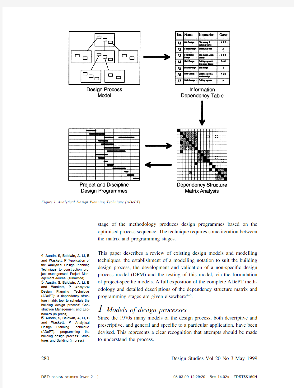
I n recent times there has been a growing understanding of the impor-tance of effective design management to facilitate a coordinated design within budget,and to ensure the smooth running of the project.Tra-ditionally,building design has been planned by the same methods used to programme construction.These techniques do not allow the effect of vari-ations and delays to be fully understood within an iterative process such as design.They monitor progress based upon the completion of drawing work and other ‘design deliverables’as opposed to the availability of key pieces of information.The ADePT methodology shown in Figure 1was devised to overcome these limitations 1,and associated computer tools have been developed to facilitate more effective planning and management of building design 2.The ?rst stage of the methodology is a model of the building design process,representing design activities and their information requirements.The data in this model are linked via a dependency table to a dependency structure matrix (DSM)analysis tool 3which is used in the second stage to identify iteration within the design process and schedule the activities with the objective of optimising the task order.The third
1Austin,S,Baldwin,A and
Newton,A ‘A data ?ow model to
plan and manage the building
design process’Journal of
Engineering Design Vol 7No 1
(1996)pp 3–252Austin,S,Baldwin,A,Li,B
and Waskett,P Development of
the ADePT methodology:an
interim report on the link IDAC
100Project Loughborough Uni-
versity,Loughborough (1998)3Steward,D Analysis and
management:structure,strategy
and design Petrocelli Books,
Princeton,NJ,USA (1981)0142-694X/99$-see front matter Design Studies 20(1999)279–296
279
PII:S0142-694X(98)00038-6
?1999Elsevier Science Ltd All rights reserved Printed in Great Britain Analytical Design Planning Technique:a model of the detailed building design process
Simon Austin,Andrew Baldwin,Baizhan Li and Paul Waskett,
Department of Civil and Building Engineering,Loughborough
University,Loughborough LE113TU,UK
Current planning practice takes little account of the interdisciplinary,
iterative nature of the building design process.This leads to a
compromised design process containing inevitable cycles of rework
together with associated time and cost penalties in both design and
construction.The Analytical Design Planning Technique (ADePT)is a
planning methodology which helps to overcome these dif?culties.This
paper describes the development of a modelling notation and model of
the detailed building design process,which forms the ?rst stage of
ADePT.?1999Elsevier Science Ltd.All rights reserved
Keywords:design management,design techniques,modelling,planning,
information processing
4Austin,S,Baldwin,A,Li,B
and Waskett,P ‘Application of
the Analytical Design Planning
Technique to construction pro-
ject management’Project Man-
agement Journal (submitted)5Austin,S,Baldwin,A,Li,B
and Waskett,P ‘Analytical
Design Planning Technique
(ADePT):a dependency struc-
ture matrix tool to schedule the
building design process’Con-
struction Management and Eco-
nomics (in press)6Austin,S,Baldwin,A,Li,B
and Waskett,P ‘Analytical
Design Planning Technique
(ADePT):programming the
building design process’Struc-
tures and Building (in press)stage of the methodology produces design programmes based on the
optimised process sequence.The technique requires some iteration between
the matrix and programming stages.
This paper describes a review of existing design models and modelling techniques,the establishment of a modelling notation to suit the building design process,the development and validation of a non-speci?c design process model (DPM)and the testing of this model,via the formulation of project-speci?c models.A full exposition of the complete ADePT meth-odology and detailed descriptions of the dependency structure matrix and programming stages are given elsewhere 4–6.1Models of design processes Since the 1970s many models of the design process,both descriptive and prescriptive,and general and speci?c to a particular application,have been devised.This represents a clear recognition that attempts should be made to understand the process.
280Design Studies Vol 20No 3May 1999
Figure 1Analytical Design Planning Technique (ADePT)
7Pugh,S‘Design activity mod-els:worldwide emergence and convergence’Design Studies Vol7No3(1986)pp167–173 8VDI-Richtlinie2221
(Entwurf)Methodik zum
entwickeln und konstruieren technischer systeme und pro-dukte VDI-Verlag,Du¨sseldorf (1985)
9Pahl,G and Beitz,W Engin-eering design:a systematic approach The Design Council, London(1988)
10RIBA Plan of Work for Design Team Operation Royal Institute of British Architects, RIBA Publications,London (1973)
11Pugh,S and Morley,I E Total design:towards a theory of total design Design Division,Uni-versity of Strathclyde,Glasgow (1988)
12Pugh,S Total design Wiley, London(1990)
13Sheath,D M,Woolley,H, Cooper,R,Hinks,J and Aouad,G A Process for change—the development of a generic design and construction protocol for the UK construction industry In International Con-struction Information Technology (INCIT96)Conference Sydney, Australia(1996)
14Sanvido,V E and Norton,
KJ‘Integrated design-process model’Journal of Management in Engineering Vol September/October(1994) pp55–62
15Karhu,V,Keitila¨,M and Lahdenpera¨,P Construction process model:generic present-state systematisation by IDEF0 Research Notes1845VTT,Fin-land(1997)
16Baldwin,A,Austin,S,
Thorpe,A and Hassan,T Simu-lating quality within the design process.In American Society of Civil Engineers(ASCE)Second Congress on Computing in Civil Engineering Atlanta,Georgia (1995)pp1475–14821.1Existing models of design
A literature review has identi?ed many attempts to model design in general, engineering design and parts of the building design process.The models of product and engineering design that were reviewed revealed two recurring themes.Most models represent the process at a‘high level’,acting as an overview of the process,containing very little in the way of detail.The second recurring feature is that,by accident or design,they describe the overall process in terms of the stages within it.Among the best known models is Pugh’s7‘total design’model,generically covering all design processes.The VDI model of engineering design8and the Pahl and Beitz9 design model represent two of the best known models of engineering design.
The most widely used model of building design is the RIBA Plan of Work for Design Team Operation10.This sets out the details of work to be carried out by each profession during each stage of the design process,but differs from most other models in that it does not show‘links’of information between activities to indicate how particular tasks are related.
Pugh further developed his‘total design model’to produce a‘business design activity model’11,12.This showed how the model could be made business or industry-speci?c.By way of an example,he represented build-ing design.This model shares the same features as the‘total design model’in that it is an overview of the process.Sheath et al.13describe the basis for a model of design and construction termed the process protocol.Again this model examines the process at an overview level in terms of its stages but is also divided into eight management functions,including design man-agement.Collaborative research is currently underway to build a second level of detail into the protocol,which will have linkages with the model described here.
Sanvido and Norton14produced a high level model of building design using an established modelling technique termed IDEF0(Integrated Computer-aided Manufacturing De?nition),and therefore differing from most other models because the system of representation followed set rules.Karhu et al.15also adopted the IDEF0technique to model the building design and construction process at a high level.The approach of using a recognised notation to construct a model had not been considered by the producers of most other models.However,Austin et al.1and Baldwin et al.16have com-bined the level of detail in the RIBA Plan of Work with information‘links’to achieve in-depth models of the different stages of the building design process using data?ow diagrams.Data?ow diagrams enable a model to be devised at the overview level,and then decomposed to reveal?ner
Analytical Design Planning Technique:a model of the detailed building design process281
17Marca,D A and McGowen, C L SADT:Structured Analysis and Design Technique McGraw-Hill,New York(1988)
18Bravoco,R R and Yadav, S B A‘Methodology to model the dynamic structure of an organis-ation’Information Systems Vol 10No3(1985)pp299–317
19Court,A W,Culley,S J and McMahon,C A‘Information access diagrams:a technique for analysing the usage of design information’Journal of Engineer-ing Design Vol7No1(1996) pp55–75detail.Baldwin et al.16produced a model of the concept and scheme design stages of a project,while Austin et al.1developed a model of the civil and structural engineering elements of the detailed design stage.These works, and those of Sanvido and Norton14and Karhu et al.15,each developed a model of building design using a recognised modelling technique because they required their models to be of use as part of broader,more com-plex systems.
1.2Modelling techniques
Many modelling methodologies have been examined to identify one that is most suited to representing information?ow in detailed building design. Possible methodologies include:data?ow diagrams;IDEF techniques (including IDEF0);entity relationship diagrams;hierarchical plus input–process–output diagrams;Jackson diagrams;object-orientated modelling systems;and Petri nets.Each of these techniques has advantages in model-ling certain types of activity or data.Data?ow diagrams and IDEF0were identi?ed as the most suitable techniques to produce a model of building design for use in the wider context of the ADePT methodology.The two techniques offer similar features,but data?ow diagrams were originally favoured because of the work of Austin et al.1.However,following a detailed evaluation of the two methodologies and a review of recent trends in process modelling,it was decided that IDEF0would be the most appro-priate notation.
1.2.1IDEF0modelling
The IDEF methodologies were devised in the1970s for use in the US aerospace industry.By the mid-1970s they were in use in Europe and are now notable among modelling techniques for their wide range of usage, particularly IDEF017.IDEF techniques were developed in order to better communicate and analyse manufacturing in an attempt to improve pro-ductivity.This would be achieved through modelling information,dynam-ics and functions and processes18.Court et al.19undertook a comparison of various modelling techniques,including the IDEF techniques.Functional modelling is achieved with IDEF0.A process can be represented from the viewpoint of the information within it,rather than of its subprocesses, which has been identi?ed as a requirement of a building design model. The technique is easy to use and understand,which is very important if the model is to be modi?ed very quickly at the start of a building project and maintained throughout it.Each activity in the process transforms an information input into an output,and the internal mechanics of that trans-formation are not modelled.Figure2shows the notation of the IDEF0 technique.Each activity or process can be partitioned to show?ner detail on another diagram,ensuring a single diagram does not become too cum-bersome.
282Design Studies Vol20No3May1999
In most respects,the features of IDEF0models are the same as data ?ow
diagrams.The common features of IDEF0modelling and data ?ow dia-
grams are:they are capable of top–down analysis;the top–down nature of
the methods allows the top parts to be read to obtain an overview of the
system and if more detail is required the lower levels can be studied;they
are easily readable because of their graphical nature;the models are a
manageable size (no diagram is larger than an A4sheet);they represent a
system from a viewpoint of data rather than a viewpoint of an organisation
so a model can represent more than one organisation’s operations;the con-
sistency of the diagrams can be easily checked;they can model iterative
procedures;they can model the aspect of choice;they do not describe how
a task should be done,just what is needed to perform that task and what
it is transformed into;and they do not show a sequence of activities.The
distinguishing features of IDEF0are that it emphasises the ?ow and control
of data and process mechanisms or resources can be represented,while
data ?ow diagrams allow the physical source of data to be shown.IDEF0
diagrams have a number of characteristics that mean they require careful
use and a clear understanding to be maintained:they appear,at a super?cial
level,deceptively simple in their presentation and use;they can give a
‘false sense’of sequence;and it is dif?cult,at a glance,to decide where
some of the data has originated from.These disadvantages were out-
weighed by the bene?ts of adopting the IDEF0methodology,particularly
if it is modi?ed to suit the characteristics of the building design process.
1.2.2
IDEF0v:a modi?ed version of the IDEF0
technique
The review of the IDEF0methodology found that although the technique
is suitable to model the detailed building design process,some modi?-
cations could be made to the notation to enhance its advantages,parti-
cularly with the control and resource.The purpose of the ADePT model
is to represent information requirements (i.e.constraints)and not to indi-
cate how each design task should be undertaken.In this context there is Analytical Design Planning Technique:a model of the detailed building design process 283Figure 2IDEF0
notation
little bene?t to be gained from representing separate process controls in
the model.Also,activity mechanisms (architect,civil engineer,etc.)would
show little other than the discipline to which the activity belongs,and this
attribute is implicit from the hierarchical structure of the model.It was
decided that better use could be made of the top and bottom arrow features
of an IDEF0diagram by distinguishing the information inputs that are from
activities in the same discipline,from those in other disciplines and from
external sources such as the client,a regulating authority or an earlier stage
of the design process.Discussions with designers and design managers
suggest that this is of bene?t,since the different types of information ?ow
require different management priorities.
Figure 3shows the notation implemented in the detailed building design
process model,termed IDEF0v,which varies from the standard IDEF0
notation in the following ways:
(1)intra-disciplinary inputs enter from the left;
(2)cross-disciplinary inputs enter from the top;and
(3)inputs from external sources enter from the bottom.
Tools that enable IDEF0models to be constructed automatically dis-
tinguish between the different types of information input in a diagram.
These tools will allow a model using IDEF0v to be compiled and will
be able to distinguish between the different information inputs in their
reporting facilities.
2Creating the design process model
The DPM of detailed building design was developed in two stages.
Initially,the activities within the overall process were identi?ed and their
hierarchical structure determined.Then the information requirements of
284Design Studies Vol 20No 3May 1999Figure 3Modi?ed
IDEF0
notation
(IDEF0v)
each bottom level task were identi?ed,allowing the DPM to be con-
structed.This combination of top–down and bottom–up analytical activities
and the general features of the model are described below.
2.1
Identifying the detailed building design hierarchy and tasks 2.1.1Determining the design process hierarchy
The overall process of detailed building design is de?ned in terms of a
number of subprocesses and problems.Through a series of interviews with
designers,design managers and design planners,this research has estab-
lished a hierarchy of the subprocesses.
At the highest level is the process of detailed building design which is
then partitioned into the subprocesses shown in Figure 4.
The subprocesses are the design of all systems within the scope of responsi-
bility of each of the ?ve main design disciplines.Within each of the disci-
plines,designers were interviewed to determine the systems of the building
that normally fall within the responsibility of that discipline,and also those
that do so occasionally.The building’s systems were then organised so
they were within the part of the DPM that was deemed most appropriate.
Discussions with designers then established how the design of each system
of the building should be divided into subsystems and components and
how these should be further divided into the bottom level individual design
tasks.The hierarchy of the process shows that detailed building design is
partitioned into disciplines,systems,subsystems or components and indi-
vidual design tasks.The latter can be associated with the design of a
component,a group of components or part of a component and is not
partitioned further.Normally it is these individual design tasks that are
represented in the dependency structure matrix and programming stages of
the ADePT methodology,although analysis at a more abstract level is
sometimes a helpful precursor.
Analytical Design Planning Technique:a model of the detailed building design process 285Figure 4Detailed building
design process divided by
discipline
2.1.2Determining the information requirements of the
tasks
Having established the hierarchy of the activities in the detailed building
design process,the information dependencies of each individual design
task needed to be determined so that the DPM could be constructed.This
information was collated in tabular form,via input from practising design-
ers.The nature and source of each item of information was listed,regard-
less of whether it would normally have been available during the design
of a building.This means that all the information required to allow the
design to proceed was considered.The task number of both the task under
consideration and the source activities within the same design discipline
were determined by the process hierarchy.
2.1.3Producing design process model diagrams
The DPM was compiled with a Computer-aided Software Engineering
(CASE)tool,by placing on to each diagram the activities identi?ed in the
process hierarchy and the information?ows that each activity required.
The source activity of each intra-and cross-disciplinary information input
was then identi?ed.This was necessary because at the stage when infor-
mation requirements were determined,the precise source of each item of
information could not be known,only its discipline.The information?ows
were then attached to the appropriate tasks as either inputs or outputs using
the IDEF0v notation described in Figure3.The DPM consists of some
150diagrams,600design tasks and4600information requirements.
Figure5shows examples of diagrams from the detailed building design
model.The DPM hierarchy can be traced from activity A3,‘structural
design’,through activity A34,‘secondary structure design’,and A342,‘lift
shaft structure design’to design tasks at the bottom of the hierarchy
(activities A3421,A3422,A3423).Activity A31,‘check/revise structural
design information’is also an individual design task.It is not partitioned
or represented in the matrix analysis stage of the methodology because it
deals with grouped information rather than information produced and
required by other design tasks.It can be seen that detailed information
?ows are represented at the bottom level of the hierarchy;however,at
upper levels,the information?ows are grouped under headings that ensure
the diagrams do not become too confusing.
2.2Verifying the design process model
Following its compilation,the consistency and integrity of each section of
the building DPM was checked by the research team through the use of
functions within the proprietary CASE tool.The diagrams were then exam-
ined by designers from a different organisation to the one which helped 286Design Studies Vol20No3May1999
Analytical Design Planning Technique:a model of the detailed building design process 287
Figure 5Examples of design process diagrams:A3→A34→A342
in compiling them.This was,in effect,the ?rst test of the hypothesis relat-
ing to the construction of a largely non-speci?c (i.e.generic)design process
for buildings,and the result was very encouraging,considering the small
and relatively trivial changes required to suit the second https://www.wendangku.net/doc/bf1534158.html,-
ments were incorporated into the diagrams,where appropriate,before a
second version of the diagrams was sent to both the design organisations
for ?nal comments and con?rmation.The resulting non-speci?c design pro-
cess model was then used as the basis for the creation of project-speci?c
models on the case study projects (section 5).Clearly,further veri?cation
of the model will occur as it is exposed to more design organisations
and projects.
2.3Design information classi?cation
2.3.1Compiling design information classi?cations
The dependency structure matrix analysis stage of the ADePT methodology
not only represents the activities in the DPM and the dependencies between
them,but indicates the level of dependency and schedules the process on
this basis.The information requirements were tabulated in the same form
as was used to compile the https://www.wendangku.net/doc/bf1534158.html,rmation classi?cations were allocated
to each information ?ow by practising designers from the collaborating
organisations.Classi?cations were made on a three-point scale,A being
the most critical information and C being the least.Where a generic classi-
?cation could not be determined,designers indicated that there would be
more than one possible classi?cation depending on the features of the pro-
ject.This meant that six alternative generic classi?cations were made:A,
B,C,A/B,B/C and A–https://www.wendangku.net/doc/bf1534158.html,rmation classi?cations were made on the
basis of three factors;strength of dependency of the task on the infor-
mation;sensitivity of the task to slight changes in the information;and the
ease with which the information can be estimated,as shown in Figure 6.
2.3.2Verifying design information classi?cations
The table of information classi?cations was veri?ed by designers from an
alternative organisation to the one which supplied information compiled
288Design Studies Vol 20No 3May 1999Figure 6Contrasting in?u-
ences on information classi-
?cations
1
the https://www.wendangku.net/doc/bf1534158.html,ments and suggestions were evaluated and discussed with
both the designers responsible for compiling and verifying the information,
before?nalising the generic information classi?cations table.
3Features of the design process model
3.1Discipline-speci?c features
The hierarchical structure of the building DPM has different characteristics
for each discipline because of variations in the way the disciplines under-
take their work.This applies particularly to architecture and engineering.
The following section describes the main structure of the DPM within each
discipline,summarising the breakdown into systems of the building and
then into subsystems and components.
The architectural design process(activity A1)contains a series of activities
related to the design of architectural systems.The design tasks within the
architectural section of the model are closely associated with the production
of drawings and speci?cations.This is markedly different from the engin-
eering disciplines’design processes,where tasks are more concerned with
the development of the design,and is a re?ection on the way architects
work.The architectural development of the design is largely completed
prior to the detailed design stage of the building project,and therefore work
undertaken during the stage is primarily in the production of drawings.
The civil and structural engineering processes(activities A2and A3)are
subdivided into the design of systems in a similar manner to architecture.
The division between the civil and structural engineering disciplines occurs
at ground level of a building,as agreed with practising designers during
the DPM creation and veri?cation.The design of the ground?oor slab and
systems beneath it are civil engineering activities,while the design of
above ground systems are represented within the structural engineering
model.A further feature of the civil engineering section of the DPM is
that it contains‘options’for various systems of the building.For example,
two options exist for the design of foundations:‘piled foundation design’
and‘spread foundation design’.
The mechanical engineering section(activity A4)is subdivided into the
design of a range mechanical services systems.The design of each mechan-
ical services system is decomposed further into‘requirements and load
analysis’,‘schematic design’,‘plant layout design’and‘system speci?-
cations’which are in turn broken down into individual design tasks.
Like the mechanical engineering discipline,the electrical engineering
section of the DPM(activity A5)is divided into engineering systems. Analytical Design Planning Technique:a model of the detailed building design process289
However,at the?rst partition the electrical engineering process is rep-
resented in terms of‘groups’of systems such as‘lighting systems design’
and‘communications systems design’before being decomposed further
into systems such as‘general lighting design’and‘emergency lighting
design’and then into individual design tasks.
3.2Cross-disciplinary characteristics of the design
process model
3.2.1Structure
The detailed building design process is decomposed into design activities
to be undertaken by the?ve design disciplines:architecture,civil engineer-
ing,structural engineering,mechanical engineering and electrical engineer-
ing.It is apparent from interviews with design managers that in some cases,
more than these?ve disciplines may be involved in the design.For
example,public health engineering and?re engineering are regularly
undertaken by specialist consultants.These instances need to be noted at
the beginning of a project so that either the DPM can be modi?ed to show
the specialist disciplines,or the activities within the scope of responsibility
of the specialist disciplines can be highlighted at the programming stage.
The building’s systems appear in the hierarchy under the discipline where
they best suit the design and management methods of the design organis-
ations interviewed during the research.In some cases,it would be appropri-
ate for the design of systems to be undertaken by designers in a discipline
other than the one indicated by the DPM.Examples of instances where
design could feasibly be undertaken by more than one discipline are:lifts
(architectural or electrical engineering);foundations(civil engineering or
structural engineering);and external works(architectural or civil
engineering).Again,these issues need to be noted at the beginning of a
project so that either the DPM can be modi?ed accordingly,or the activities
can be allocated to the appropriate discipline at the programming stage.
The scope of the DPM and the information within it attempt to describe
the process at a non-speci?c level.That is to say that the DPM represents
the process of design of a building which contains common systems and
elements,including suitable options where appropriate.As a result of this,
at the stage where the model is used to represent the design process for a
speci?c project,it will require some manipulation to represent the process
accurately.This will mean that some sections of the DPM will have to be
deleted(for example,one of the options for‘foundation design’would
normally be deleted),some sections added and some altered(for instance,
some information?ows may need to be reviewed to account for the
location of components in the building).The extent of the applicability of 290Design Studies Vol20No3May1999
the model to a range of building types can only be ascertained by its
repeated application to new projects,with the expectation that it will evolve
and increase in genericicity.As will be shown later,the current model
accounted for over90%of the design activities in the test projects.
3.2.2System,components and activities
Each activity in the DPM in referenced with a unique number.This num-
ber,which is pre?xed with the letter A(for activity),indicates the location
of the activity within the process hierarchy.For example;design task
‘LPHW(low pressure hot water)pipe work pressure loss calculation’is
activity number A4324which is the fourth task at a level below A432,
‘LPHW schematic design’,in the hierarchy which is in turn below A43,
‘LPHW system design’,and A4,‘mechanical services design’.
Each system within the building is represented once in the DPM.However,
in some projects various parts of the building may be present more than
once,for example,two or more specialist lighting systems may be required.
Where this is the case,the relevant part of the DPM will need to be dupli-
cated together with the corresponding information?ows.
The choice of some systems of the building is dependent on the construc-
tion methods being used,the site,the client and other in?uences.This
means that options for different types of system need to be included in the
DPM.For example,a number of different foundation design,power supply
design,and lighting design activities exist.Any of these activities that are
not required during a project must be removed from the DPM at the begin-
ning of the design.
Activities are described by a noun.For example,‘general lighting layouts’,
‘lift requirements’or‘steam heating load calculation’.The procedure itself
is that of performing,determining or establishing the activity described.
3.2.3Information?ows
At the high levels of the DPM,information?ows are grouped to ensure
that the diagrams do not become unwieldy.For example,at the level of
the?ve main disciplines,all information is grouped into intra-disciplinary
design information,cross-disciplinary design information,and draft(or
unchecked)design information.At levels in the DPM where grouped infor-
mation is separated,the name under which it was grouped at the higher
level will be shown.This allows information?ows to be traced through
the levels of the hierarchy quickly.Grouped information will always be
separated at the lowest level of the hierarchy,or at a higher level when
this can by achieved without making the diagram https://www.wendangku.net/doc/bf1534158.html,rmation Analytical Design Planning Technique:a model of the detailed building design process291
inputs from external sources are not grouped at higher levels of the DPM
but are‘tunnelled’(shown in brackets).This is a technique that ensures
the DPM’s consistency remains intact.
Where an input is required by an activity from an external source,then
the name of the source is given,thereby indicating the origin of the infor-
mation rather than the nature of the information itself.This is so that a
designer can see from the DPM the person to liaise with in order to get
the required information.The nature of the information is normally obvious
from its source and from the activity it is required by.This approach aims
to distinguish between the information from external sources such as stan-
dards,design guides,or a previous stage in the design process which should
be readily available to the designers,and external bodies,where it will be
more dif?cult to ensure that the information?ows are timely.
4Modelling design information location
The aim of the building DPM is to show the design tasks indicate the
information requirements of these tasks and to identify the source of each
item of information.This will then allow the sequencing and programming
of the design to take place based on the?ow of information within the
process.In order to gain the full bene?ts of the model and programmes
based upon it,not only does the nature of the design information need to
be represented but also the location of the information within the project.
Therefore,it is a further aim of the DPM to de?ne the location of the
information illustrated in the model to help coordinate storage,access
and retrieval.
The location of documented information within the design process can be
described by de?ning the documents or deliverables that are produced dur-
ing the detailed design in terms of the information that they show.This will
in turn have de?ned a generic list of project deliverables to be produced as
a result of completing the tasks described by the DPM.
4.1Design deliverables matrix
Research into the number and nature of typical drawings and schedules
produced during the detailed design stage of a project has produced a sum-
mary of the usual deliverables.This is shown in Table1,which lists the
deliverables in terms of the system with which they are concerned and the
type of document that is being produced for the electrical engineering part
of the DPM.Table1also highlights the task within the model that is
responsible for producing the deliverable.Obviously,with an array of
information on each deliverable,there are often a number of tasks that
contribute to their production.The task number given in the table relates 292Design Studies Vol20No3May1999
20Ray-Jones,A and
McCann,W CI/SfB project man-
ual:organising building project
information Royal Institute of
British Architects,the Architec-
tural Press,London (1971)to the individual task that is responsible for the production of the document
(which will contain information produced by other tasks).
4.2Design deliverable de?nitions
The CI/SfB Construction Indexing Manual 20gives brief de?nitions of some of the types of document produced during a building design.In order to facilitate the easy location of design information,de?nitions of the various design documents (calculations,location drawings,schematic drawings,etc.)have been formulated,some of which are based on those in the CI/SfB Construction Indexing Manual but updated and with a more detailed description.The design deliverables matrix (Table 1)and the de?nitions of each type of deliverable mean that,having identi?ed the information requirements of a design task by using the DPM,the designer should be able to locate the document or documents on which that information is shown.
Analytical Design Planning Technique:a model of the detailed building design process 293Table 1Design deliverables matrix for electrical engineering
Calculations
Drawings Schedules Specs Building element/system Locaton Schematics GAs Layouts Assembly Compo-
Detail nent
High voltage supply and
A5211A52113A52121A5212A52122A5211A5213distribution
Low voltage supply and
A5221A52213A52221A52221A52222A5221A5223distribution
Electrical carcassing
A523A523A5233Small power
A524A5244A5245Standby generator
A5251A5252/3A5254A5244A5257Uninterruptable power supply
A5261A5262A5263Emergency lighting
A5311A5313/5A5312A5317General lighting
A5321A5324/8A5323A5326A5.3.2.10External lighting
A5331A5333A5332A5335A5337Specialist lighting
A5341A5343A5342A5345A5347Telecomms
A5412A5413A5417Paging and staff location
A5421A5423A5424A5426Public address
A5433A5432A5434A5436Radio and TV
A5442A5441A5443/4A5447A5448Clocks
A5451A5452/3A5453A5455A5454A5457Data transmission
A5462A5461A5465A5466A5467Access control
A5511A5512/5A5512A5516Intruder detection
A5522A5523/6A5527CCTV
A5532A5531/6A5533/4A5538Fire detection and alarm
A5611A5612A5613/6A5617Earthing and bonding
A5623A5625A5626Lightning protection
A56324A5635A5636Lifts
A5711A5715A5713A5714A5717Escalators
A5721A5723A5726Moving pavements
A5731A5733A5736Hoists
A5741A5745A5746Cranes
A5751A5753A5754Central monitoring A581A582A584A585
5Validation and application
The non-speci?c DPM has been validated by producing four project-spe-
ci?c models and testing the matrix analysis and programming stages of
ADePT on them.A project-speci?c representation of the design process
can be developed in one of three ways:
?the CASE tool can be used to amend the model diagrams before a
project-speci?c table of information dependencies is produced;
?a table of information dependencies and classi?cations based on the
non-speci?c DPM can be amended before a dependency structure
matrix(DSM)is developed;and
?a DSM produced directly from the non-speci?c DPM can be amended.
Testing to date shows that each approach has bene?ts and disadvantages
over each other in terms of the time taken,ease of operation and accuracy
of modelling.Future work will focus on the model’s interface with a Win-
dows-style approach to manipulating the model.
The DPM has been tested on a pharmaceutical laboratory,a railway ter-
minal,an of?ce development and a hospital.These projects ranged in value
from£16M to£160M,and Table2gives details of the size and complexity
of the models.This small number of test cases places limits on the vali-
dation process,but the results(described below)indicate that the attempt
to produce a reasonably generic model,which requires relatively little
effort to convert for a speci?c building,has been successful.
Table2Results of applying the DPM to building projects
Project A B C D Description Pharmaceutical Railway Of?ce Hospital
laboratory terminal development
No.of design tasks Deleted207261242212
Added1228671
Reproduced2380348
Total410357346789 No.of tasks Architecture51
in each discipline Civil eng.9
common to all projects Struct.eng.26
Mech.eng.91
Elec.eng.104
Relevant proportion of generic model tasks91%96%99%91% No.of data?ows28042804265610,015 Hours to generate16201240 294Design Studies Vol20No3May1999
This testing of the DPM has meant that a broad range of design issues has
been included in the model validation to date.In formulating a project-
speci?c model of the design process,the?rst task is in ensuring the model
content and structure is valid.The former requires the deletion of design
activities that are not relevant to the project,and the addition of activities
associated with speci?c features of the building not already covered.There
may also be occasions where a section of the model must be duplicated,
for example,where more than one type of ventilation system is to be
designed,then the appropriate section of the model must be repeated.The
validity of the model was con?rmed further by the largely repeatable nature
of its structure,evident from the suitability of a high proportion of tasks
to a diverse range of projects,as can be seen in Table2.A limited number
of civil and structural tasks are applicable to each of the projects because
of the different types of structure(foundations,ground?oor slab,frame,
etc.)designed in each project.Table2shows that despite this,relatively
few additions were necessary to compile the model during its testing on
the three projects,as various choices for different structural systems are
included in the non-speci?c model.
The second task in modelling a speci?c project was to review the infor-
mation requirements of all design tasks.Again,this meant deleting(and,
on occasions,adding or redirecting)information?ows in the model.
6Conclusions
This paper has described a model of the detailed building design process
that is the?rst stage of the Analytical Design Planning Technique
(ADePT).The model has been developed through the production of a
revised IDEF0process modelling notation termed IDEF0v,the implemen-
tation of a three-point information classi?cation system and the formulation
of an information location matrix and deliverables de?nitions.The model,
information classi?cations and information matrix have been veri?ed
across two organisations and the model has been tested by successfully
representing the design of four building projects.It has proved possible to
generate the project-speci?c models in an acceptable time scale.With time,
the database of the DPM will grow,increasing its generic nature and reduc-
ing the need for special project additions.
The design process model covers a wide range of building systems.This
means that the design activities and information dependencies in complex
building design problems can be represented and the ADePT planning
methodology can be used to programme and manage the design phase of
such projects.Practising designers and design managers shown the ADePT
methodology have been enthusiastic about the effectiveness of the
approach and the detailed nature of the DPM.
Analytical Design Planning Technique:a model of the detailed building design process295
21RIBA Uniclass:uni?ed classi?cation for the construction industry Royal Institute of British Architects,RIBA Publications, London(1997)Further work will examine the hierarchy of the DPM in relation to the Uniclass system of structuring project information21,investigate the relationships between the detailed design stage(represented by the DPM) and other stages of the design process,study various means of formulating project-speci?c models and test the DPM and ADePT methodology on further building projects.
Acknowledgments
This work has been undertaken as part of a project entitled‘Design Infor-mation Methodology and Tools for the Management of Detailed Building Design’.The research is funded under research grant GR/K74197by the EPSRC,DETR and industry(AMEC Design,Ove Arup and Partners, BAA,Boots,Laing Management and Sheppard Robson).
296Design Studies Vol20No3May1999
技术开发部管理手册1
目录 第1章概述 (1) 1.1 技术开发部管理权限 (1) 1.2 技术开发部管理职能 (1) 1.3 技术开发部主要职责 (1) 1.4 日常管理制度 (2) 第2章产品开发设计控制程序 (4) 2.1 目的 (4) 2.2 范围 (5) 2.3 引用文件及术语 (5) 2.4 职责 (5) 2.5 工作程序 (6) 2.6 支持文件 (9) 2.7 表格清单 (9) 2.8 附表 (9) 第3章产品实现的策划程序 (17) 3.1 目的 (17) 3.2 适应范围 (17) 3.3 引用文件及术语 (18) 3.4 职责 (18) 3.5 工作程序 (18) 3.6 支持性文件 (19) 第4章内部质量审核控制程序 (20) 4.1 目的 (20) 4.2 适用范围 (20) 4.3 引用文件及术语 (20) 4.4 职责 (20) 4.5 工作程序 (21) 4.6 支持文件 (23) 4.7 质量记录 (23) 附录 (25) 附录1 (25) 附录2 (26) 附录3 (27) 附录5 (29) 附录6 (30) 附件7 (31) 附件8 (32)
第1章概述 技术开发部的工作主要是从事电表、水表、煤气表及其远程自动抄系统的研发和产品的优化,以及为生产部和工程部提供技术支持等。 1.1 技术开发部管理权限 受总经理和技术总监委托,行使对公司技术引进、新产品开发研究、新技术推广应用、技术指导与监督等全过程听管理权限,并承担执行公司规章制度、管理规程及工作指令的义务; 1.2 技术开发部管理职能 负责对公司产品实行技术指导、规范工艺流程、制定技术标准、抓好技术管理、实施技术监督和协调的专职管理部门,对所承担的工作负责。 1.3 技术开发部主要职责: 1.坚决服从总经理和技术总监的统一指挥,认真执行其工作指令,一切管理行为向总经理和技术总监负责; 2.严格遵守公司规章制度,认真履行其工作职责; 3.负责制定公司技术管理制度。负责建立和完善产品设计、新产品的试制、标准化技术规程、技术情报管理制度,组织、协调、督促有关部门建立和完善设备、质量、能源等管理标准及制度; 4.组织和编制公司技术发展规划。编制近期技术提高工作计划,编制长远技术发展和技术措施规划,并组织对计划、规划的拟定、修改、补充、实施等一系列技术组织和管理工作; 5.负责制订和修改技术规程。编制产品的使用、维修和技术安全等有关的技术规定; 6.负责公司新技术引进和产品开发工作的计划、实施,确保产品品种不断更新和扩大; 7.合理编制技术文件,改进和规范工艺流程; 8.研究和摸索科学的流水作业规律,认真做好各类技术信息和资料收集、整理、分析、研究汇总、归档保管工作,为逐步实现公司现代化销售的目标,提供可靠的指导依据; 9.负责制定公司产品的企业统一标准,实现产品的规范化管理; 10.编制公司产品标准,按年度审核、补充、修订定额内容;
汽车新产品质量管理手册
浙江吉利控股集团有限公司企业标准
浙江吉利控股集团有限公司 新产品质量管理手册 (第1版)V1.0 浙江吉利控股集团有限公司 2011-11-25发布 2011-12-30实施
说明 为贯彻集团“两个转型”和“两个调整”的经营工作思路,实现从“产品线管理”向“品牌线管理”的调整,规范和细化集团新产品项目质量管理过程,明确质量系统各单位在新产品质量管理过程中的职责及工作内容,使实际工作开展有规可循,并强化可操作性,特制定此《吉利集团新产品质量管理手册》(第1版),版本号为V1.0。
目录 第一章新产品质量管理总则 第二章新产品质量评审流程 第三章新产品品熟推进流程 第四章附录
第一章 新产品质量管理总则 1.1目的 为了规范集团新产品开发各阶段的质量管理,促进各部门在新品阶段的质量自主管理能力,并以用户满意为最终目标,展开各阶层新产品质量管理。 1.2范围 本手册适用于以下项目范围:整车开发项目,发动机开发项目,变速器开发项目等各类将以量产形式生产并销售的新产品正式立项开发项目(具体项目分类界定规则参照《研发项目管理办法 V2.1》,涉及具体工作开展项目范围时,可由关联单位协商界定)。 1.3新产品质量管理模式 集团新产品质量管理采用由集团质量管理部建立统一的管理体系,各品牌质量部主导策划管控及实施,各系统分级管控的模式。通过前期的弱点项目(雷区项目)设计输入、依托各新产品项目品熟团队,以不断循环展开的阶段质量阀评审以及品熟活动,达成新产品质量保证,最终实现用户满意。新产品质量管理对新产品整体项目质量负责,确保新产品项目质量达标,满足设计和市场要求。新产品质量管理绩效评价按集团质量部相关考核指标展开(参看集团质量体系考核相关文件)。 1.3.1新产品质量管控过程 新产品质量管理涉及集团项目管理流程全部三个阶段: 1.3.1.1立项阶段的质量管控 在新产品立项阶段,质量部门负责项目质量策划,并向项目组输出项目各阶段项目质量目标、《质量目标保障计划书》,以及过往和在产产品设计相关弱点问题清单(雷区项目),全部内容均可包含在《质量目标保障计划书》中一并提交。 1.3.1.1.1 新产品质量目标的策划(包括各开发试制阶段及量产阶段) ·质量目标设定的原则: -新产品质量目标的设定应与集团的经营战略相一致; -新产品的质量目标应根据车型平台特征、市场分析、过往质量水平进行各阶段的目标设定(数据来源包括设计、采购、制造、市场等各产品过程相关部门),并在各阶段质量评审中进行考评; -质量目标应包括反映设计改善、制造、市场、供应商品质等各领域产品及过程相关的指标内容,具体可根据项目实际进行增加或删减。基础项目请参考《第四章 附录》中的《质量目标基础项目表》。 目标设定后应向各质量责任单元分解,并制定相应的质量目标保障措施。 立项阶段 实施与控制阶段 关闭阶段
Allegro表贴类元件焊盘与封装制作
手工制作表贴类元件封装 1贴片元件焊盘制作 1.1打开 Pad Designer PCB Editor Utilities > Pad Desig ner 1.2Layers 选项勾选 Signle layer mode ( Parameters 选项不做设置) 可在Parameters>Summary 查看到Single Mode: on,制作贴片类元件焊盘必须勾选。 1.3BEGIN LAYER 顶层(焊盘实体):在Regular Pad (常规焊盘)中,选择Geometry下拉列表,确认焊盘的型状,输入焊盘的width、height。 (注意:贴片类元件焊盘Thermal Relief > Anti Pad选择Null。) 焊盘形状: Null (空)、Circle (圆形)、Square (正方形)、Oblong (椭圆形)、Rectangle (长方形)、Octagon (八边形)、Shape (形状、任意形状) 1.4PASTEMASK_TOP 钢网层、锡膏防护层:印锡膏用,为非布线层,与BEGIN LAYER的设置一致。 1.5SOLDERMASK_TOP 阻焊层:绿油开窗(就是焊盘与绿油中间位置,没铜皮也没绿油),焊盘尺寸比BEGIN LAYER大(IPC 7351标准),自已设置大2mil。 (这里的2mil是指边到边,如果是个正方形焊盘,那么soldermask的边长比焊盘的实际边长要大4mil,BGA的焊盘也不例外。) 1.6焊盘保存 File下拉菜单中,选择Save/Save as,保存焊盘(保存至symbols文件夹内),焊盘制 作完成。 2贴片元件封装制作 2.1打开 PCB Editor PCB Editor >Allegro PCB Desig n GXL 2.2新建封装符号 File> New,弹出New Drawing对话框,Drasing Name输入新建圭寸装的名称,点击Browse 选择圭寸装存放的路径,Drawing Type 选择Package symbol。 2.3设置制作封装的图纸尺寸、字体设置 图纸尺寸:Setup>Desig n Parameter Editor>Desig n ,Comma nd parameters 中Size 选择Other,Accuracy (单位精度)填4 ;将Extents 中:Left X、Lower Y (绝对坐标,中心原点,都设置为图纸大小的一半,这样就保证原点在图纸正中间位置)进行设置;图纸尺寸一般可设置为Width (600mil )、Height (600mil),这样制作为元件封装,可减小存储空间。 字体设置: 2.4设置栅格点大小Setup>Grid,Spacingx、y 方便封装制作。 2.5加载已制作好的焊盘Layout>P in 右侧Options选项 Connect (有电气属性):勾Or Text Seup Width Hraght 、」 1mil,Offsetx、y 设 0,,将栅格设置为1mil, 2l^https://www.wendangku.net/doc/bf1534158.html, 3|38.0Q 4147.00 5BG.OO 占驗庐nic |25.0C |3fli0 ESOO /b.UU lf l 11 - t- n |93.0Q [riTno 131.00 ■I11 Fl 1药B ia& iio iiri i i i
(完整版)新产品开发项目管理制度
新产品开发项目管理制度 1.目的和作用 新产品开发是企业在激烈的技术竞争中赖以生存和发展的命脉,它对企业产品发展方向、产品优势、开拓新市场、提高经济效益等方面起着决定性作用。为了使新产品开发能够严格遵循科学管理程序进行,取得较好的效果,特制定本制度。 2.管理职责 2.1统筹规划部负责新产品的调研分析与立项等方面的工作。 2.2技术研发部负责产品的设计、试制、鉴定、移交投产等方面的管理。 2.3物控部、生产部、质管部应在整个开发过程中给予支持和配合。 3.新产品开发的前期调研分析工作 新产品的可行性分析是新产品开发不可缺少的前期工作,必须在进行充分的技术和市场调查后,对产品的社会需要、市场占有率、技术现状、发展趋势以及资源效益等五个方面进行科学预测及经济性的分析论证。 3.1 调查研究: 3.1.1 调查国内市场和重要用户以及国际重点市场的技术现状和改进要求. 3.1.2 以国内同类产品市场占有率高的前三名以及国际名牌产品为对象,调查同类产品的质量、价格及使用情况。
3.1.3 广泛收集国内外有关情报和专利,然后进行可行性分析研究. 3.2 可行性分析: 3.2.1 论证该产品的技术发展方向和动向. 3.2.2 论证市场动态及发展该产品具备的技术优势. 3.2.3 论证该产品发展所具备的资源条件和可行性(含物资、设备、能源、外购外协配套等)。 3.2.4 初步论证技术经济效益。 3.2.5 写出该产品批量投产的可行性分析报告。 4. 产品设计管理 产品设计时从确定产品设计任务书起到确定产品结构为止的一系 列技术工作的准备和管理,是产品开发的重要环节,必须严格遵循"三 段设计"程序. 4.1 技术任务书: 技术任务书市产品在初步设计阶段内,由设计部门向上级提出的 体现产品合理设计方案的改进性和推存性意见的文件,经上级批准后,作为产品技术设计的依据.其目的在于正确地确定产品的最佳总体设计方案、主要技术性能参数、工作原理、系统和主体结构,并由设计员负责编写(其中标准化规则要求会同标准化人员共同拟定)。现对其编写内容和程序作如下规定: 4.1.1 设计依据(根据具体情况可以包括一个或数个内容): a. 国内外技术情报:在市场的性能和使用性方面赶超国内外先进水平,或在产品品种方面填补国内"空白".
新产品开发的管理制度
新产品开发管理制度 新产品开发工作,是指运用国内外在基础研究与应用研究中所发现的科学知识及其成果,转变为新产品、新材料、新生产过程等一切非常规性质的技术工作。新产品开发是企业在激烈的技术竞争中赖以生存和发展的命脉,是实现“生产一代,试制一代,研究一代和构思一代”的产品升级换代宗旨的重要阶段,它对企业产品发展方向,产品优势,开拓新市场,提高经济效益等方面起着决定性的作用。因此,新产品开发必须严格遵循产品开发的科学管理程序,即选题(构思、调研和方案论证)_样(模)试_批试_正式投产前的准备这些骤。 新产品的可行性分析是新产品开发中不可缺少的前期工作,必须在进行充分的技术和市场调查后,对产品的社会需求、市场占有率、技术现状和发展趋势以及资源效益等五个方面进行科学预测及技术经济的分析论证。 (一)调查研究: 1.调查国内市场和重要用户以及国际重点市场同类产品的技术现状和改进要求; 2.以国内同类产品市场占有率高的前三名以及国际名牌产品为对象,调查同类产品的质量、价格、市场及使用情况; 3.广泛收集国内外有关情报和专刊,然后进行可行性分析研究。 (二)可行性分析: 1.论证该类产品的技术发展方向和动向。 2.论证市场动态及发展该产品具备的技术优势。 3.论证发展该产品的资源条件的可行性。(含物资、设备、能源及外购外协件配套等)。 (三)决策: 1.制定产品发展规划: (1)企业根据国家和地方经济发展的需要、从企业产品发展方向、发展规模,发展水平和技术改造方向、赶超目标以及企业现有条件进行综合调查研究和可行性分析,制定企业产品发展规划。 (2)由研究所提出草拟规划,经厂总师办初步审查,由总工程师组织有关部门人员进行慎密 的研究定稿后,报厂长批准,由计划科下达执行。 2.瞄准世界先进水平和赶超目标,为提高产品质量进行新技术、新材料、新工艺、新装备方面的应用研究: (1)开展产品寿命周期的研究,促进产品的升级换代,预测企业的盈亏和生存,为企业提供产品发展的科学依据; (2)开展哪些对产品升级换代有决定意义的科学研究、基础件攻关、重大工艺改革、重大专用设备和测试仪器的研究; (3)开展哪些对提高产品质量有重大影响的新材料研究; (4)科研规划由研究所提出草拟规划交总师办组织有关部门会审,经总工程师签字报厂长批准后,由计划科综合下达。
手工绘制元件封装
DUPLICATE”的空元件封装,如图2所示 图1 元件封装向导 图2 库中显示空元件封装名光标指到该封装名称处,单击鼠标右键,在弹出的菜单中执行的对话框中更改封装名称为“DIP16”,然后单击 对全部高中资料试卷电气设备,在安装过程中以及安装结束后进行高中资料试卷调整试验;通电检查所有
图4 封装库参数设置对话框 在该对话框中,板面参数分组设置:Unit 】(度量单位):用于设置系统度量单位。系统提供了两种度量单位,即公制),系统默认为英制。 、管路敷设技术定盒位置保护层防腐跨接地线弯曲半径标高等,要求技术交底。管线敷设技术中包含线槽、管架等多项方式,为解决高中语文电气课件中管壁薄、接口不严等问题,合理利用管线敷设技术。线缆敷设原则:在分线盒处,当不同电压回路交叉时,应采用金属隔板进行隔开处理;同一线槽内,强电回路须同时切断习题电源,线缆敷设完毕,要进行检查和检测处理。、电气课件中调试校对图纸,编写复杂设备与装置高中资料试卷调试方案,编写重要设备高中资料试卷试验方案以及系统启动方案;对整套启动过程中高中资料试卷电气设备进行调试工作并且进行过关运行高中资料试卷技术指导。对于调试过程中高中资料试卷技术问题,作为调试人员,需要在事前掌握图纸资料、设备制造厂家出具高中资料试卷试验报告与相关技术资料,并且了解现场设备高中资料试卷布置情况与有关高中资料试卷电气系统接线等情况,然后根据规范与规程规定,制定设备调试高中资料试卷方案。 、电气设备调试高中资料试卷技术中资料试卷工况进行自动处理,尤其要避免错误高中资料试卷保护装置动作,并且拒绝动作,来避免不必要高中资料试卷突然停机。因此,电力高中资料试卷保护装置调试技术,要求电力保护装置做到准确灵活。对于差动保护装置高中资料试卷调试技术是指发电机一变压器组在发生内部故障时,需要进行外部电源高中资料试卷切除从而采用高中资料试卷主要保护装置。
新产品开发与管理手册
新产品开发与管理手册 主办:上海普瑞思管理咨询有限公司 2010年11月29—30日北京11月25—时间: 2010年10月28—29日深圳 10月25—26日杭州? 26日上海 2010年12月30—31日北京12月27—28日深圳 价格:¥2200 /人(包括授课费、资料费、会务费、证书、午餐等) 【培训对象】企业CEO/总经理、研发总经理/副总,公司总工/技术总监,公司人力资源总监、产品线总监、产品经理/项目经理、PMO(项目管理办公室)成员、市场总监、技术支持总监等。 【课程背景】 2008年一场金融风暴席卷全球,大量的工业企业倒闭关门,大批员工失业。在这场金融危机中我们发现还是有很多企业不但没有倒下,反而更加高速成长,其中一个重要的原因就是这些企业构建了成功的产品管理体系,培养了优秀的产品经理,能够组织团队开发出具有竞争力、满足客户需求的产品。公司在冬天更应该加强自己内功的修炼来应对危机,同时迎接春天的到来。 当一个企业从单一产品线向多产品线跨越的时候,必须突破的一个瓶颈就是公司产品经理的培养,因为产品经理是公司价值链中最重要的一个环节,是直接面向客户、带领团队创造价值的领军人物,因此产品经理个人及其所率领的团队的能力往往决定了该产品在市场上的竞争力。业界大量公司在构建产品管理体系和培养产品经理的过程中常见如下困惑的问题: 1.产品经理该如何定位?究竟定位于研发还是定位于市场? 2.产品经理和项目经理有什么区别?如何作好分工??3.产品经理究竟应该具有什么样的素质模型?谁来承担 比较合适? 4.产品经理如何参与产品的市场管理流程?如何从源头来规划产品??5.如何推动产品开发全流程的工作??6.如何协调产品的市场管理、开发管理、财经管理之间的关系? 7.产品经理如何管理产品团队? 8.公司如何建立产品经理的培养体系以成批培养产品经理? 本课程在过去4年讲授的基础上作了大量的更新,结合业界成功公司在产品经理培养和管理上的一些教训和经验,针对以上难题进行深入的讲解,并总结出如何建立公司的产品经理资源池来批量培养成功的产品经理,实现公司规模化的扩张。 ?≡≡≡≡≡≡≡≡≡≡≡≡≡≡≡≡≡≡≡≡≡≡≡≡≡≡≡≡≡≡≡≡≡≡≡≡≡≡ 【课程收益】 1.分享讲师数百场研发管理培训的专业经验,通过现场的互动帮助学员理清适合自己企业的产品管理的思路和产品经理的培养方案 2.分析业界公司在产品经理培养和管理中的误区,并分享成功经验?3.了解产品经理的定位、职责、素质模型与任职资格标准 4.理解新产品市场管理、路标规划、需求管理的流程及支撑体系 5.掌握新产品开发的过程管理的技巧和方法? 6.掌握新产品上市管理的技巧和方法,总结保证产品商业成功的关键? 7.学会如何打造一个成功的产品团队,如何管理产品团队的绩效和冲突处理 8.学会如何建立产品经理的培养体系――资源池
ad绘制元件封装操作总结
发光二极管:颜色有红、黄、绿、蓝之分,亮度分普亮、高亮、超亮三个等级,常用的封装形式有三类:0805、1206、1210 二极管:根据所承受电流的的限度,封装形式大致分为两类,小电流型(如1N4148)封装为1206,大电流型(如IN4007)暂没有具体封装形式,只能给出具体尺寸:5.5 X 3 X 0.5 电容:可分为无极性和有极性两类,无极性电容下述两类封装最为常见,即0805、0603;而有极性电容也就是我们平时所称的电解电容,一般我们平时用的最多的为铝电解电容,由于其电解质为铝,所以其温度稳定性以及精度都不是很高,而贴片元件由于其紧贴电路版,所以要求温度稳定性要高,所以贴片电容以钽电容为多,根据其耐压不同,贴片电容又可分为A、B、C、D四个系列,具体分类如下: 类型封装形式耐压 A 3216 10V B 3528 16V C 6032 25V D 7343 35V 拨码开关、晶振:等在市场都可以找到不同规格的贴片封装,其性能价格会根据他们的引脚镀层、标称频率以及段位相关联。 电阻:和无极性电容相仿,最为常见的有0805、0603两类,不同的是,她可以以排阻的身份出现,四位、八位都有,具体封装样式可参照MD16仿真版,也可以到设计所内部PCB库查询。 注: A\B\C\D四类型的封装形式则为其具体尺寸,标注形式为L X S X H 1210具体尺寸与电解电容B类3528类型相同 0805具体尺寸:2.0 X 1.25 X 0.5 1206具体尺寸:3.0 X 1.5 0X 0.5 ***规则 印制电路板(PCB)是电子产品中电路元件和器件的支撑件。它提供电路元件和器件之间的电气连接。随着电子技术的飞速发展,PCB的密度越来越高。PCB 设计的好坏对抗干扰能力影响很大。实践证明,即使电路原理图设计正确,印制电路板设计不当,也会对电子产品的可靠性产生不利影响。例如,如果印制板两条细平行线靠得很近,则会形成信号波形的延迟,在传输线的终端形成反射噪声。因此,在设计印制电路板的时候,应注意采用正确的方法,遵守PCB设计的一般原则,并应符合抗干扰设计的要求。 一、 PCB设计的一般原则 要使电子电路获得最佳性能,元器件的布局及导线的布设是很重要的。为了设计质量好、造价低的PCB,应遵循以下的一般性原则: 1.布局 首先,要考虑PCB尺寸大小。PCB尺寸过大时,印制线条长,阻抗增加,抗噪声能力下降,成本也增加;过小,则散热不好,且邻近线条易受干扰。在确定PCB尺寸后,再确定特殊元件的位置。最后,根据电路的功能单元,对电路的全部元器件进行布局。 在确定特殊元件的位置时要遵守以下原则: (1)尽可能缩短高频元器件之间的连线,设法减少它们的分布参数和相互间的电磁干扰。
新产品研发管理制度.doc
新产品研发管理制度第一条目的和作用 1.1 新产品研发是企业在激烈的市场竞争中赖以生存和发展的创新活动,对 企业产品发展方向、巩固产品优势、开拓新市场、提高经济效益等方面起着决 定性作用。为了使新产品开发能够严格遵循科学管理程序进行,取得较好的效果,特制定本制度。 1.2 本制度中所指的新产品的研发包括新产品开发和产品的持续改进。 第二条管理职责 2.1 技术中心负责新产品的市场调研分析、立项、设计、开发、验证、试制、移交投产等工作。 2.2 生产部、质检部、销售部(含外贸部)、供应部等部门应在新产品研发 过程中给予支持和配合。 第三条新产品研发的前期调研分析工作 新产品的可行性分析是新产品研发不可缺少的前期工作,必须在进行充分的 技术和市场调研后,对产品的社会需要、市场占有率、技术现状、发展趋势以及资源效益等多方面进行综合的科学预测及经济性的分析论证。 3.1 调查研究 3.1.1 调查国内市场和重要用户以及国际重点市场的技术现状和改进要 求。 3.1.2 以国内同类产品市场占有率高的前三名以及国际同类名牌产品为对 象,调查同类产品的质量、价格、市场及使用等情况。 3.1.3 广泛收集国内外有关情报和专利,然后进行可行性分析研究。 3.2 可行性分析
3.2.1 论证拟新发产品的技术发展方向和动向。 3.2.2 论证拟新研发产品的市场动态及发展该产品具备的技术优势。 3.2.3 论证拟新研发产品发展所具备的资源条件和可行性(含物资、设备、 能源、外购外协配套设施等)。 3.2.4 初步论证拟新研发产品的技术经济效益和社会效益。 第四条新产品研发管理 4.1 研发项目的立项与实施研发 4.1.1 技术中心填报《 XXX项目建议书》(见附件1),上报公司批准后,确定立项。技术中心下达《设计开发任务书》(见附件2)给研发项目负责人。 4.1.2 研发项目负责人根据《设计开发任务书》编制《设计开发方案》(详见附件 3)和《设计开发计划书》(详见附件 4),并组织项目小组进行新产品研发工作。 4.2 研发过程的管理与控制 4.2.1 研发项目负责人根据研发项目进度,在小试、中试阶段提出评审需 求,由技术中心组织人员进行评审,并出具《设计开发评审报告》(详见附件 5)。 4.2.2 研发项目负责人根据《设计开发评审报告》组织项目组对项目进行 改进、继续开发,至试产,填报《试产总结报告》报技术中心和公司审核。确定 投入大批量生产的,报公司总经理批准。 4.2.3 技术文件资料的验收及存档。技术中心负责将全部文件收齐归档, 资料管理人员存档时必须验证齐全。 4.3 知识产权登记与管理 在不泄露公司技术秘密的前提下,公司认为有必要申请国家知识产权的研发技术或产品,有研发项目组负责提供相关的技术资料和文件,技术中心只是产权管理人员负责相关申请报批工作。
新产品开发和上市管理制度
新产品开发和上市管理制度 1目的 对新产品开发和上市的全过程进行控制,确保产品能满足顾客的需求和期望及符合有关法律、法规要求。 2范围 适用于本公司新产品的开发与上市管理。 3职责 3.1 市场部负责项目的立项归口管理。 3.2 总经理负责批准项目立项。 3.3 研发中心负责新产品配方设计、试验评价、技术标准的组织管理工作。 3.4 财务部负责成本核算。 3.5 生产部及品控部参与新产品加工工艺及生产条件的确认、试生产活动。 销管部负责收集顾客使用新产品后的意见或建议并反馈信息。 4内容 4.1项目的立项确认 市场部根据本部门对市场的调研和了解,以《产品开发项目立项书(讨论稿)》的形式提出立项建议,组织相关部门召开专题会对立项书内容进行讨论,并将讨论的结果进行分析整理,形成正式的《产品
开发项目立项书》后报总经理审批。 4.2 开发计划书的确认 立项确认后,市场部组织相关部门讨论确定开发计划,根据讨论结果完成《产品设计开发计划书》,下发各相关部门,各部门根据推进计划中的时间安排制定本部的工作计划。在项目推进过程中,市场部将在必要时向相关部门通报项目进展情况,如有特殊情况,市场部将以专题会议或书面形式通知各相关部门。 4.3开发计划的实施 4.3.1产品小试阶段 a.研发中心通过技术资料的搜集,设计新产品的试验方案,试验方案包括:试验配方、工艺过程等内容。 b.新产品使用的原辅料原则上以公司现有的原辅料优先选择,若为公司内部没有的原辅料,可联系厂家索取样品。必要时可请采购部协助解决。 c.新产品经过反复试验和改进后,可将认为满意的产品在研发中心内部进行品尝。品尝通过后,组织公司内部品尝并填写《产品综合品评表》和《样品品评结果处置表》。 d.公司内部品尝前,应依据新产品不同的特点,设定相应的通过标准,超过评定标准时,则视为新产品小试通过。如内部品尝未能通过,则应对新产品继续进行试验和改进。 e.小试产品品评通过后方可进行中试申请。 4.3.2中试阶段
如何绘制贴片元件封装
1、我们建议自己创建的元件库保存在另外的磁盘分区,这样的好处是如果在Protel DXP软件出现问题或操作系统出现问题时,自己创建的元件库不可能因为重新安装软件或系统而丢失,另外对元件库的管理也比较方便和容易。 2、对于自己用手工绘制元件时必须注意元件的焊接面在底层还是在顶层,一般来讲,贴片元件的焊接面是在顶层,而其他元件的焊接面是在底层(实际是在MultiLayer层)。对贴片元件的焊盘用绘图工具中的焊盘工具放置焊盘,然后双击焊盘,在对话框将Saple(形状)中的下拉单修改为Rectangle(方形)焊盘,同时调整焊盘大小X-Size 和Y-Size为合适的尺寸,将Layer(层)修改到“Toplayer”(顶层),将Hole Size(内经大小)修改为0mil,再将Designator中的焊盘名修改为需要的焊盘名,再点击OK就可以了。有的初学者在做贴片元件时用填充来做焊盘,这是不可以的,一则本身不是焊盘,在用网络表自动放置元件时肯定出错,二则如果生产PCB板,阻焊层将这个焊盘覆盖,无法焊接,请初学者们特别注意。 3、在用手工绘制封装元件和用向导绘制封装元件时,首先要知道元件的外形尺寸和引脚间尺寸以及外形和引脚间的尺寸,这些尺寸在元件供应商的网站或供应商提供的资料中可以查到,如果没有这些资料,那只有用千分尺一个尺寸一个尺寸地测量了。测量后的尺寸是公制,最好换算成以mil为单位的尺寸(1cm= 1000/2.54=394mil 1mm=1000/25.4=39.4mil),如果要求不是很高,可以取1cm=400mil,1mm=40mil。 4、如果目前已经编辑了一个PCB电路板,那么单击【Design】/【Make PCB Library】可以将PCB电路板上的所有元件新建成一个封装元件库,放置在PCB文件所在的工程中。这个方法十分有用,我们在编辑PCB文件时如果仅仅对这个文件中的某个封装元件修改的话,那么只修改这个封装元件库中的相关元件就可以了,而其他封装元件库中的元件不会被修改。
(完整版)管理手册8.3设计和开发2016
8.3.产品和服务的设计和开发 8.3.1.总则 公司产品和服务的设计和开发由技术质保部归口管理,设计和开发活动应明确设计和开发的目的,公司制定和实施《产品和服务的设计和开发控制程序》,对设计和开发的策划、输入、过程控制、输出及更改做出具体规定。 8.3.2.设计和开发策划 8.3.2.1.根据公司确定的年度产品开发任务或者顾客要求等,由技术质保部 进行设计和开发的策划,设计和开发的策划需考虑以下内容: a)设计和开发活动的性质(如:全新产品设计、升级产品设计、客户订制产品 等)、持续时间和复杂程度; b)所需的过程阶段,包括适用的设计和开发评审; c)所需的设计和开发验证及确认活动; d)设计和开发过程涉及的职责和权限; e)产品和服务的设计和开发所需的内部和外部资源; f)设计和开发过程参与人员之间接口的控制需求; g)顾客和使用者参与设计和开发过程的需求; h)后续的产品和服务提供的要求; i)顾客和其他相关方期望的设计和开发过程得控制水平; j)证实已满足设计和开发要求所需的文件记录。 8.3.2.2.设计和开发的策划应形成《设计和开发计划书》。 8.3.3.设计和开发输入 8.3.3.1.设计和开发前,应针对具体类型的产品和服务确定设计和开发的基 本要求,形成设计和开发的输入,设计和开发的输入是设计和开发过程 的依据,设计和开发的输入应包括: a)产品和服务有关功能和性能要求。这类要求来自顾客或市场的需求期望(包 括顾客期望但没有表述出来的愿望或潜在的需求)及本公司确定的要求,一般包含在合同或研发项目建议书等技术文件中; b)适用的以前类似设计活动提供的信息; c)适用的法律法规要求、承诺执行的标准或行业规范,对国家强制性标准及规
产品开发手册
版本号:B/0 页次:第1页共102页实施日期:2006.3.28 奇瑞汽车有限公司 新产品开发手册 编制/日期:过成军/2006.3.21 审核/日期:孙久红/2006.3.21 批准/日期:尹同耀/2006.3.28
修订页 编制/修订原因说明: 修订 原章节号现章节号修订内容说明备注编制/修订部门/人项目管理部/过成军 参加评审部门/人汽车工程研究院、规划设计院、采购公司、销售公司、国际公司、质量保证部、备件公司、物流公司、项目管理部、轿车公司、发动机公司、变速箱公司、信息技术部等 修订记录: 版本号提出部门/人修订人审核人批准人实施日期备注B/0 项目管理部/过成军过成军孙久红尹同耀2006.3.28
前言 本产品开发手册是在项目管理部、前企业管理部、汽车工程研究院、规划设计院、采购公司、销售公司、国际公司、质量保证部、备件公司等相关部门系统梳理新产品开发流程及其内部工作流程的基础上,共同研讨后完成的。 该手册告诉我们,产品“开发”不是产品研发部门一个部门的工作,而是所有与之相关的所有部门(包括外协单位)的共同工作。只是在不同的开发阶段,不同的部门参与的工作量不同。因此,一个新产品的开发,需要所有相关部门的共同参与,提前介入,才能保证信息的沟通,各环节连接顺畅。 而各部门的共同参与是建立在各部门分工明确的基础之上的。手册规定了每个部门在每个阶段应完成哪些工作;为启动某个阶段的工作,必须具备哪些前提条件;而完成这一阶段以后,应该完成哪些工作。即每个阶段均有明确的入口与出口,并由谁完成这些任务。 产品开发是一个“过程”。本手册阐述了以全新平台开发为模板的新产品开发过程。而车型开发和变型开发仅是该过程的简化,其内容可在具体的项目计划、项目定义与策划中进一步明确。产品开发的每个过程所需时间是客观存在的,如果违反这一规律要求,某些缺陷将会带给下一步工作引起返工;甚至影响市场信誉。 该手册的编制工作从2005年5月起至今,共10个月的时间。由于时间紧迫和对该手册的理解尚处于初始阶段,因此,我们肯请各相关部门能与我们共同探讨如何使该手册在我公司发挥更大的效益,缩短产品开发周期,规范产品开发行为,提高产品的竞争性,迎接市场的挑战。 在该手册编制过程中,我们得到了公司领导及相关部门的大力支持和帮助,在此,我们表示衷心的感谢。 项目管理部 2006年3月
PCB电路板PPCB元件封装和库制作图文详解
PCB电路板PPCB元件封装和库制作图文详解
PowerPCB元件封装制作图文详解!新手一定要看! PowerPCB元件封装制作图文详解! ***************************************************我们习惯上将设计工作分为三大阶段,指的是前期准备阶段、中间的设计阶段以及后期设计检查与数据输出阶段。前期准备阶段的最重要的任务之一就是制作元件,制作元件需要比较专业的知识,我们会在下一部教程中专门介绍。但是学会了做元件只是第一步,因为元件做好后还必须保存起来,保存的场所就是我们现在要讨论的元件库,而且在PowerPCB中只有将元件存放到元件库中之后,才能调出使用。因此做元件与建元件库操作是密不可分的,有时还习惯将两个操作 合而为一,统称为建库。 建库过程中的重要工作之一就是对元件库的管理,可以想像一个功能强大的元件库,至少要能满足设计者的下列几方面的要求:必须能够随意新建元件库、具有较强的检索功能、可以对库中的内容进行各种编辑操作、可以将元件库中的内容导 入或者是导出等等。 下面我们将分几小节对PowerPCB元件库的各种管理功能进行详细讨论。 一,PowerPCB元件库基本结构 1.元件库结构 在深入讨论之前,有必要先熟悉PowerPCB的元件库结构,在下述图9-1已经打开的元件库管理窗口下,我们可以清晰地看到四个图标,它们分别代表
PowerPCB的四个库,这是PowerPCB元件库的的一个重要特点。换句话说,每当新建一个元件库时,其实都有四个子库与之对应。有关各个库的含义请仔细 阅读图9-1说明部分。 图9-1各元件库功能说明 例如我们新建了一个名为FTL的库后,在Padspwr的Lib目录下就会同时出现四个名称相 同但后缀名各异的元件库,如图9-2分别为: FTL.pt4:PartType元件类型库 FTL.pd4:PartDecal元件封装库 FTL.ld4:CAE逻辑封装库 FTL.ln4:Line线库 这是Padspwr的Lib目录下的所有元件库的列表,在这里可以找到所有元件库,包括系统 自带的与客户新建的库。
新产品开发管理制度新编
一、总则 第一条在进行产品开发前必须进行调查研究,调查研究的工作包括:1.调查国内市场和重要用户以及国际重点市场同类产品的技术现状和改进要求。 2.以国内同类产品市场占有率的前三名以及国际名牌产品为对象,调查同类产品的质量、价格、市场及使用情况。 3.广泛收集国内外有关情报和专刊,然后进行可行性分析研究。 第二条可行性分析的工作有: 1.论证该类产品的技术发展方向。 2.论证市场动态及发展该产品具备的技术优势。 3.论证发展该产品的资源条件的可行性。 第三条制定产品发展规划: 由研究所提出草拟规划,经公司总工程办公室初步审查,由总工程师组 织有关部门人员进行缜密研究,定稿后报公司批准,由计划科下达执行。第四条产品开发研究所的主要职责是: 1.开展产品生命周期的研究,促进产品的升级换代,预测企业的盈亏,为企业提供产品生产的科学依据。 2.开展对产品升级换代具有决定意义的基础科学研究、重大工艺改革、重大专用设备和测试仪器的研究。 3开展那些对提高产品质量有重大影响的新材料研究。 二、新产品试制工作规定 第五条新产品试制是在产品按科学程序完成“三段设计”的基础上进行的,是正式投入批生产的前期工作,试制一般分为样品试制和小批试制两个阶 段。
第二十八条从高等院校或有关科研设计机构引进的经过实验考核的产品,必须索取全部论证、设计和工艺(含工具)的技术资料,并应重新调查分 析论证。这类产品的开发周期定为2~5个月。 第二十九条属于已有产品在性能和结构原理上有较大的改变的研究以及新类别的产品的开发,开发周期一般定为6~7个月,最长为一年(特别 情况下超过一年半时间),具体程序周期规定为: 1.调研论证和决策周期:一般产品一个月,复杂产品一个半月。 2.产品设计周期(含技术任务书、技术设计和工作图设计):1~2个月。 3.工艺(含工具)设计周期:1~2个月。 4.产品试制(含工具制造)周期:1~2个月。 5.样品试制周期:1~2个月(含样品鉴定)。 6.小批量试制周期:2~35个月。 7.产品鉴定和移交生产周期:1个月。 六、新产品成果评审和报批规定 第三十条新产品根据鉴定级别,按照国务院、国家科委有关科技成果与技术进步有关奖励条例和本公司《关于技术改进与合理化建议管理办法》办理 报审手续。 第三十一条为节省开支,新产品(科研)成果评审会应尽量与新产品鉴定会合并进行。 第三十二条成果报审手续必须在评审鉴定后一个月内办理完毕。 第三十三条成果奖励分配方案由公司研究所共同商定后报总工程师批准执行。
技术开发部管理手册1
目录 第1章概述1 1.1 技术开发部管理权限1 1.2 技术开发部管理职能1 1.3 技术开发部主要职责1 1.4 日常管理制度2 第2章产品开发设计控制程序4 2.1 目的4 2.2 X围5 2.3 引用文件及术语5 2.4 职责5 2.5 工作程序6 2.6支持文件9 2.7表格清单9 2.8 附表9 第3章产品实现的策划程序17 3.1 目的17 3.2 适应X围18 3.3 引用文件及术语18 3.4 职责18 3.5 工作程序18 3.6 支持性文件19 第4章内部质量审核控制程序20 4.1 目的20 4.2 适用X围20 4.3 引用文件及术语20 4.4 职责21 4.5 工作程序21 4.6 支持文件24 4.7 质量记录24 附录26 附录126 附录227 附录328 附录530 附录630 附件731 附件832
第1章概述 技术开发部的工作主要是从事电表、水表、煤气表及其远程自动抄系统的研发和产品的优化,以及为生产部和工程部提供技术支持等。 1.1 技术开发部管理权限 受总经理和技术总监委托,行使对公司技术引进、新产品开发研究、新技术推广应用、技术指导与监督等全过程听管理权限,并承担执行公司规章制度、管理规程及工作指令的义务; 1.2 技术开发部管理职能 负责对公司产品实行技术指导、规X工艺流程、制定技术标准、抓好技术管理、实施技术监督和协调的专职管理部门,对所承担的工作负责。 1.3 技术开发部主要职责: 1.坚决服从总经理和技术总监的统一指挥,认真执行其工作指令,一切管理行为向总经理和技术总监负责; 2.严格遵守公司规章制度,认真履行其工作职责; 3.负责制定公司技术管理制度。负责建立和完善产品设计、新产品的试制、标准化技术规程、技术情报管理制度,组织、协调、督促有关部门建立和完善设备、质量、能源等管理标准及制度; 4.组织和编制公司技术发展规划。编制近期技术提高工作计划,编制长远技术发展和技术措施规划,并组织对计划、规划的拟定、修改、补充、实施等一系列技术组织和管理工作; 5.负责制订和修改技术规程。编制产品的使用、维修和技术安全等有关的技术规定; 6.负责公司新技术引进和产品开发工作的计划、实施,确保产品品种不断更新和扩大; 7.合理编制技术文件,改进和规X工艺流程; 8.研究和摸索科学的流水作业规律,认真做好各类技术信息和资料收集、整理、分析、研究汇总、归档保管工作,为逐步实现公司现代化销售的目标,提供可靠的指导依据; 9.负责制定公司产品的企业统一标准,实现产品的规X化管理;
Altium画元件封装
电子系科协硬件部 新版的Altium Designer10.0,针对于此版本的(也适用于更低的版本)如何画元件封装的问题,在此特作超详细的图文教程,以便广大学子可以更好的学习和使用Altium Designer10.0这个软件。 在此,大家只要跟着下面的教程一步一步的操作,就可以学会画封装的操作了 下面就以LM2586S 为例,为大家详细讲解LM2586S封装的画法。 一.目的:学会用Altium Designer 建立自己的原件库,并在里面画自己所需的元件件原理图和封装。 二.软件环境:Altium Designer 10.0 三.准备:LM2596S 的PFD 说明书。四.操作步骤: A.打开Altium Designer 10.0 新建元件库工程。 1(选项File——NEW——project——integrated Library)另存到指定文件夹,命名为my_Library。 B.向my_Library 工程中添加原理图库文件和PCB 库文件,修改命名。 1(在处点右键选Add New to Projiect ------ Schematic Library)
Project -----PCB Library ,创建后修改另存命名。) 3(创建后的结果,记得保存) C. 在 alpha.Schlib 原理图库文件中画 LM2596S 原理图 1 点击左下方 SCH Library 2 (在 处右键 Add New
2为添加一个元件原理图模型,命名为LM2596S 保存 3双击LM2596S 4修改Default Designater 为LM2596S,修改Comment为3.3v,点OK
新产品开发项目管理制度4.doc
新产品开发项目管理制度4 新产品开发项目管理制度 1.目的和作用 新产品开发是企业在激烈的技术竞争中赖以生存和发展的命脉,它对企业产品 发展方向、产品优势、开拓新市场、提高经济效益等方面起着决定性作用。为 了使新产品开发能够严格遵循科学管理程序进行,取得较好的效果,特制定本 制度。 2.管理职责 2.1统筹规划部负责新产品的调研分析与立项等方面的工作。 2.2技术研发部负责产品的设计、试制、鉴定、移交投产等方面的管理。 2.3物控部、生产部、质管部应在整个开发过程中给予支持和配合。 3.新产品开发的前期调研分析工作 新产品的可行性分析是新产品开发不可缺少的前期工作,必
须在进行充分的技 术和市场调查后,对产品的社会需要、市场占有率、技术现状、发展趋势以及资 源效益等五个方面进行科学预测及经济性的分析论证。 3.1 调查研究: 3.1.1 调查国内市场和重要用户以及国际重点市场的技术现状和改进要求. 3.1.2 以国内同类产品市场占有率高的前三名以及国际名牌产品为对象,调查同 类产品的质量、价格及使用情况。 3.1.3 广泛收集国内外有关情报和专利,然后进行可行性分析研究. 3.2 可行性分析: 3.2.1 论证该产品的技术发展方向和动向. 3.2.2 论证市场动态及发展该产品具备的技术优势. 3.2.3 论证该产品发展所具备的资源条件和可行性(含物资、设备、能源、外购 外协配套等)。 3.2.4 初步论证技术经济效益。
3.2.5 写出该产品批量投产的可行性分析报告。 4. 产品设计管理 产品设计时从确定产品设计任务书起到确定产方峁刮沟囊幌盗屑际豕ぷ鞯淖急负凸芾?是产品开发的重要环节,必须严格遵循"三段设计"程序. 4.1 技术任务书: 技术任务书市产品在初步设计阶段内,由设计部门向上级提出的体现产品合理 设计方案的改进性和推存性意见的文件,经上级批准后,作为产品技术设计的依据.其目的在于正确地确定产品的最佳总体设计方案、主要技术性能参数、工作原理、系统和主体结构,并由设计员负责编写(其中标准化规则要求会同标准化 人员共同拟定)。现对其编写内容和程序作如下规定: 4.1.1 设计依据(根据具体情况可以包括一个或数个内容): a. 国内外技术情报:在市场的性能和使用性方面赶超国内外先进水平,或在产 品品种方面填补国内"空白". b. 市场经济情报: 在产品功能、特点、形式(新颖性)等方面满足用户要求,适应市场需要,具有竞争能力。 4.1.2 产品用途及使用范围.