SAE J287-1988 DRIVER HAND CONTROL REACH

SAE Technical Standards Board Rules provide that: “This report is published by SAE to advance the state of technical and engineering sciences. The use of this report is entirely voluntary, and its applicability and suitability for any particular use, including any patent infringement arising therefrom, is the sole responsibility of the user.”
SAE reviews each technical report at least every five years at which time it may be reaffirmed, revised, or cancelled. SAE invites your written comments and suggestions.
QUESTIONS REGARDING THIS DOCUMENT: (412) 772-8512 FAX: (412) 776-0243
TO PLACE A DOCUMENT ORDER; (412) 776-4970 FAX: (412) 776-0790
SAE WEB ADDRESS https://www.wendangku.net/doc/b74028720.html,
2.2Related Publications—The following publications are provided for information purposes only and are not a
required part of this document.
2.2.1SAE P UBLICATIONS—Available from SAE, 400 Commonwealth Drive, Warrendale, PA 15096-0001.
SAE J1052 MAY87—Motor Vehicle Driver and Passenger Head Position
SAE J1516 M AR90—Accommodation Tool Reference Point
SAE J941 JUN92—Motor Vehicle Drivers’ Eye Locations
3.Definitions
3.1Driver Hand Reach Capability—The maximum reach capability of drivers in a simulated driving situation with
the non-reaching hand on the steering wheel and the right foot on the accelerator pedal.
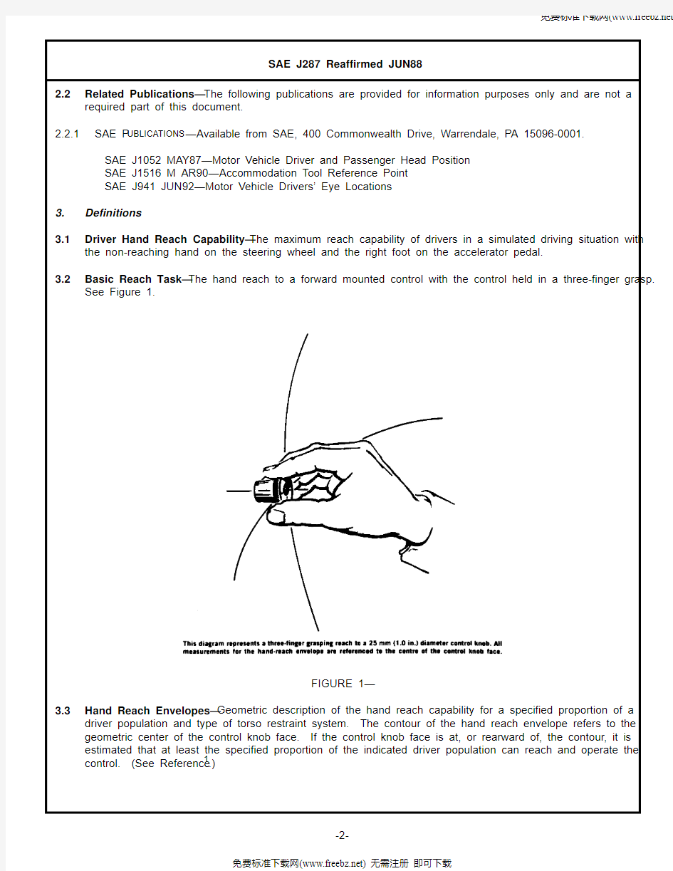
3.2Basic Reach Task—The hand reach to a forward mounted control with the control held in a three-finger grasp.
See Figure 1.
FIGURE 1—
3.3Hand Reach Envelopes—Geometric description of the hand reach capability for a specified proportion of a
driver population and type of torso restraint system. The contour of the hand reach envelope refers to the geometric center of the control knob face. If the control knob face is at, or rearward of, the contour, it is estimated that at least the specified proportion of the indicated driver population can reach and operate the control. (See Reference1.)
3.4Hand Reach Reference Plane (HR Plane)—A vertical reference plane extending laterally across the vehicle
used to properly position the hand reach envelopes with respect to the geometry of the vehicle seating configuration. The horizontal location of the HR plane rearward of the Accelerator Heel Point is determined by application of the General Package Factor (G) as shown below:
(Eq. 1)3.5Interior Dimensions—All interior dimensions referred to in this recommended practice, except where noted,
are defined in SAE J1100a—Motor Vehicle Dimensions. All dimensions are defined normal to the three-dimensional reference system of the vehicle loaded to design load weight and oriented to a ground reference plane using fiducial marks as described in SAE J182a—Motor Vehicle Fiducial Marks.The characteristics of seat geometry are described in terms of the two- and three-dimensional H-point devices with 95 percentile leg length adjustments as described in SAE J826—Devices for Use in Defining and Measuring Vehicle Seating Accommodation. The interior dimensions are measured with the front seat in the rearmost normal driving position as specified by the manufacturer. All other adjustable features, such as steering wheel, seat height, or tilt adjustment for the seat back or seat cushion, are also located as specified by the manufacturer, and if not specified will be positioned at a normal driving position.
3.5.1G ENERAL P ACKAGE F ACTOR (G)—An algebraic equation that expresses and summarizes the geometry of a
particular vehicle seating configuration in terms of a single index value. See Figures 2 and 3. The range of package dimensions for which this recommended practice is applicable is shown below:
3.5.2C ENTERLINE OF O CCUPANT (C/LO)—Centerline of occupant is the “Y” coordinate of the H-point and is
represented by the centerplane of the occupant or H-point machine in each designated seating position.
3.5.3
A CCELERATOR H EEL P OINT (AHP)—Accelerator heel point is located at the intersection of the two- or three-dimensional device heel point and the depressed floor covering with the shoe on the undepressed accelerator pedal and the foot angle at a minimum of 87 deg. For vehicles with SgRP to heel (H30) greater than 457 mm, the accelerator pedal may be depressed as specified by the manufacturer. If the depressed pedal is used, the foot must be flat on the accelerator pedal.TABLE 1—
L40Back angle-front
9.0 deg 33.0 deg H30Vertical SgRP to heel pt
130 mm to 520 mm L23Horizontal Hpt travel, SgRP
130 mm nominal W9Steering wheel diameter
330 mm to 600 mm H18Steering wheel angle
10.0 deg to 70.0 deg L11Horizontal steering wheel center 660 mm to 152 mm
H17Vertical steering wheel center 530 mm to 838 mm HR 78699() G, mm
–=
FIGURE 2—
FIGURE 3—
4.Field of Application
4.1This practice is primarily directed towards the initial design stages of a new vehicle program, where reference
to H-point or Rearmost H-point implies Rearmost Design H-point or Seating Reference Point (SgRP). Its application for checking purposes in actual vehicles and prototype seat models will take into account an allowable tolerance for actual H-point.
4.2The hand reach envelopes are directly applicable to left hand drive motor vehicles designed for seated
operators in full width or single width seats having fore and aft seat adjustment approximately horizontal.
Application to right hand drive vehicles is assumed to be symmetrically opposite.
4.3The hand reach envelopes are directly applicable for a three-finger grasping reach to a forward mounted
control knob of 25 mm diameter maneuvered horizontally in the fore-aft direction. The hand reach envelopes are also applicable to other types of reach to forward controls by using an appropriate adjustment factor that will account for the mode of operation at the control.
4.3.1E XTENDED F INGER O PERATED C ONTROL—An adjustment factor of 50 mm is added to the tabled values of the
reach envelope in order to describe the center of the finger pad contact surface which will be within the reach of drivers.
4.3.2F ULL H AND G RASPED C ONTROLS—An adjustment factor of 50 mm is subtracted from the tabled values of the
reach envelope in order to describe the center of the face of the control knob which will be within the reach of drivers.
5.Required Characteristics
5.1The ranges of the interior dimensions for which this recommended practice is applicable are described in 3.5.
5.2The envelopes describe the boundaries of control locations that can be reached by at least 95% of certain
driver populations that include mixtures of 50/50, 75/25, and 90/10 male to female driver population ratios. The envelopes for each of these categories are described as referenced in a fore and aft direction to specified seating coordinates. The envelopes extend from 400 mm outboard to 600 mm inboard of operator centerline and from -100 mm below H-point to 800 mm above H-point. See Figure 4.
FIGURE 4—
5.3Hand reach envelopes are provided in the attached tables for seven different seating configurations, three male
to female driver population ratios and two types of restraint systems which account for drivers wearing a lap belt only permitting a free upper torso and unrestrained reach; and secondly, both lap and shoulder belt permitting only a restrained reach. The selection of an envelope for a vehicle is based on the calculated value of the General Package Factor (G), identification of the male to female driver population appropriate for the vehicle, and the identification of the appropriate restraint system. The General Package Factor (G) is calculated using the dimensions describing the vehicle seating configuration as shown in Figures 2 and 3.
5.4The Hand Reach Envelop is located in the vehicle by employing a relationship that utilizes the value of the
General Package Factor (G). The horizontal component of the envelopes is measured as a distance forward of
a Hand Reach Reference Plane. The fore and aft location of this plane rearward from the Accelerator Heel
Point is determined from the value of the General Package Factor (G) as shown in 3.4.
6.Procedure for Using the Hand Reach Envelopes
6.1The envelopes are located in the vehicle according to a set of orthogonal reference planes: A horizontal
elevation reference plane through the H-point of the rearmost normal driving position, the lateral HR plane, and
a vertical plane extending along the C/LO. See Figure 4.
6.1.1Establish a reference origin.
6.1.1.1Specify the dimensions describing the geometry of the vehicle seating configuration and calculate the
value of the General Package Factor (G) as described in Figure 3.
6.1.1.2Calculate HR from the value of the General Package Factor (G) as shown in 3.4.
6.1.1.2.1 If (HR-L53) is less than zero, then the hand reach reference plane is located longitudinally at a distance
(HR) rearward of the Accelerator Heel Point.
6.1.1.2.2 IF (HR-L53) is greater than zero, the hand reach reference plane is located longitudinally at the H-point
of the rearmost normal driving position.
6.1.2Identify the appropriate hand reach envelope.
6.1.2.1Referring to the attached tables, identify the hand reach envelope appropriate for the value of the General
Package Factor (G) calculated for this vehicle, the specified driver population, and the appropriate type of restraint system.
6.1.2.2Determine the lateral locations of the controls of interest. These locations will be described as lateral
locations from the (C/LO). Determine the height of the control above the horizontal elevation reference plane described in 6.1.
6.1.3Determine if the control is within reach.1
1.The blank areas in the hand reach tables are regions where hand reach was not measured or where design limit values could not be estab-
lished. The gray areas are regions where the difference between the hand reach model and the observed design limit values exceeded 25 mm.
The reach values shown in these areas should be used cautiously.