KFD2-UFC-EX1.D
1
2003-11-27
KFD2-UFC-Ex1.D
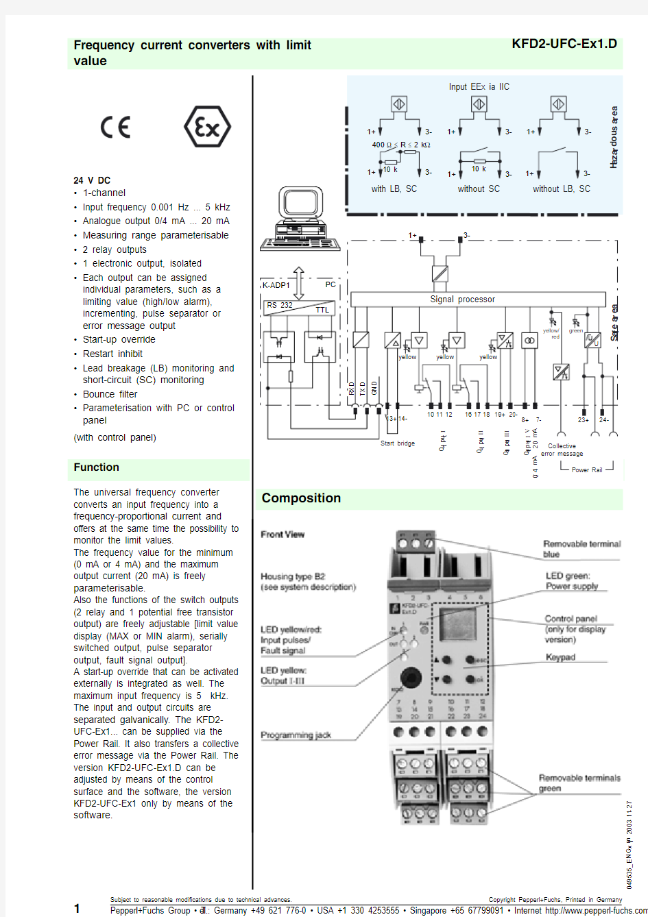
Frequency current converters with limit value
2
Technical Data
KFD2-UFC-Ex1.D
049535_E N G .x m l 2003-11-27
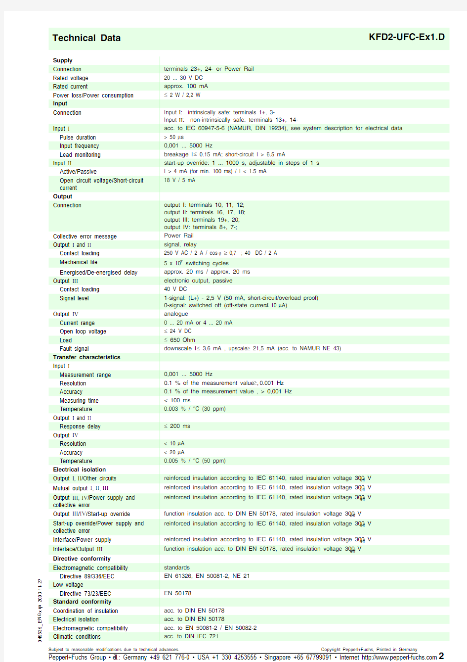
Supply
Connection terminals 23+, 24- or Power Rail Rated voltage 20 ... 30 V DC Rated current
approx. 100 mA Power loss/Power consumption d 2 W / 2,2 W
Input
Connection
Input ,: intrinsically safe: terminals 1+, 3-
Input ,,: non-intrinsically safe: terminals 13+, 14-Input ,
acc. to IEC 60947-5-6 (NAMUR, DIN 19234), see system description for electrical data Pulse duration > 50 P s
Input frequency 0,001 ... 5000 Hz
Lead monitoring breakage I d 0.15 mA; short-circuit I > 6.5 mA
Input ,,
start-up override: 1 ... 1000 s, adjustable in steps of 1 s Active/Passive
I > 4 mA (for min. 100 ms) / I < 1.5 mA Open circuit voltage/Short-circuit current 18 V / 5 mA
Output
Connection
output I: terminals 10, 11, 12; output II: terminals 16, 17, 18; output III: terminals 19+, 20; output IV: terminals 8+, 7-;Collective error message Power Rail Output , and ,,signal, relay
Contact loading 250 V AC / 2 A / cos M t 0,7 ; 40 DC / 2 A
Mechanical life 5 x 10⁷ switching cycles
Energised/De-energised delay approx. 20 ms / approx. 20 ms Output ,,,
electronic output, passive Contact loading 40 V DC
Signal level 1-signal: (L+) - 2,5 V (50 mA, short-circuit/overload proof) 0-signal: switched off (off-state current d 10 P A)Output ,9
analogue
Current range 0 ... 20 mA or 4 ... 20 mA Open loop voltage d 24 V DC Load
d 650 Ohm
Fault signal
downscale I d 3,6 mA , upscale t 21,5 mA (acc. to NAMUR NE 43)Transfer characteristics Input ,
Measurement range 0,001 ... 5000 Hz
Resolution 0.1 % of the measurement value , t 0.001 Hz Accuracy
0.1 % of the measurement value , > 0,001 Hz Measuring time < 100 ms
Temperature 0.003 % / °C (30 ppm)Output , and ,,
Response delay d 200 ms Output ,9
Resolution < 10 P A Accuracy < 20 P A
Temperature 0.005 % / °C (50 ppm)
Electrical isolation
Output ,,,,/Other circuits reinforced insulation according to IEC 61140, rated insulation voltage 300 V eff Mutual output ,,,,,,,,
reinforced insulation according to IEC 61140, rated insulation voltage 300 V eff Output ,,,,,9/Power supply and collective error
reinforced insulation according to IEC 61140, rated insulation voltage 300 V eff Output ,,,/,9/Start-up override function insulation acc. to DIN EN 50178, rated insulation voltage 300 V eff Start-up override/Power supply and collective error
reinforced insulation according to IEC 61140, rated insulation voltage 300 V eff Interface/Power supply reinforced insulation according to IEC 61140, rated insulation voltage 300 V eff Interface/Output ,,,
function insulation acc. to DIN EN 50178, rated insulation voltage 300 V eff Directive conformity
Electromagnetic compatibility standards
Directive 89/336/EEC EN 61326, EN 50081-2, NE 21Low voltage
Directive 73/23/EEC EN 50178
Standard conformity Coordination of insulation acc. to DIN EN 50178Electrical isolation
acc. to DIN EN 50178
Electromagnetic compatibility acc. to EN 50081-2 / EN 50082-2Climatic conditions
acc. to DIN IEC 721
3
049535_E N G .x m l 2003-11-2
7
KFD2-UFC-Ex1.D
Ambient conditions Ambient temperature
-20 ... 60 °C (253 ... 333 K)Mechanical specifications Protection degree IP20Mass
300 g
Data for application in conjunction with hazardous areas
EC-Type Examination Certificate
TüV 99 ATEX 1471 , for additional certificates see https://www.wendangku.net/doc/d81896579.html, Group, category, type of protection ? II (1) G D [EEx ia] IIC [circuit(s) in zone 0/1/2]Supply
Safety maximum voltage U m 40 V DC (Attention! U m is no rated voltage.)Input ,terminals 1+, 3- EEx ia IIC Voltage U o 10,1 V Current I o
13 mA
Power
P o 34 mW (linear characteristic)
Input ,,
terminals 13+, 14- non-intrinsically safe Safety maximum voltage
U m
40 V DC (Attention! U m is no rated voltage.)
Statement of conformity
TüV 02 ATEX 1885 X , observe statement of conformity Group, category, type of protection, Temperature classification ? II 3 G EEx nAC IIC T4 [device in zone 2]
Output , and II
Contact loading 253 V AC / 2 A / cos M > 0.7; 40 V DC / 2 A resistive load (TüV 99 ATEX 1471) 50 V AC / 2 A / cos M > 0.7; 40 V DC / 2 A resistive load (TüV 02 ATEX 1885 X)Output ,,,
terminals 19+, 20- non-intrinsically safe Safety maximum voltage U m 40 V DC (Attention! U m is no rated voltage.)Output ,9
terminals 8+, 7- non-intrinsically safe
Safety maximum voltage U m 40 V DC (Attention! U m is no rated voltage.)Interface
RS 232
Safety maximum voltage U m
40 V DC (Attention! U m is no rated voltage.)
Electrical isolation
Input/Other circuits safe electrical isolation acc. to EN 50020, voltage peak value 375 V Directive conformity standards
Directive 94/9 EC
EN 50014, EN 50020, EN 50021
EC-Type Examination Certificate, Statement of Conformity, Declaration of Conformity and instructions have to be observed. For information see https://www.wendangku.net/doc/d81896579.html,.
PR-03 Power Rail UPR-03 Power Rail
KFD2-EB2 power feed module
The devices are supplied with 24 VDC through the KFD2-EB2 power feed module and the PR-03 or the UPR-03 Power Rail.Each power feed module monitors and provides protection for groups of as many as 100 individual devices. The PR-03 Power Rail is an insert component for the DIN rail. The UPR-03 Power Rail is a complete unit consisting of an electrical insert and an aluminium DIN rail measuring 35mm x 15mm x 2000mm. The devices are simply snapped in place to make electrical contact.
If a Power Rail is not being used, power can be supplied to the devices directly through the device terminals.K-CJC
Removable terminals with integrated temperature measurement sensor for cold junction compensation for thermocouples.PACT ZDUH ?
Device-specific drivers (DTM)Adapter K-ADP1
Interface adapter for connection with the serial interface of a PC/Notebook.
Supplementary information
Accessories