2008省技能竞赛试题-企业网-网络设备配置v4

2008年广东省中等职业学校学生计算机技能大赛
——企业网络搭建及应用,网络设备配置部分
180分钟(满分100分,占30%)
需求分析:某企业的局域网,核心三层交换机-A 、核心三层交换机-B 、接入二层交换机、路
由及接在接入交换机下的各种业务类型的用户组成分公司业务办公局域网,为了实现网络的
稳定在网络中运行VRRP+MSTP 实现双链路双核心。要求两台核心使用端口汇聚功能提高
带宽。任何时间不允许使用QQ 聊天。
说明:文中所有出现的X 代表参赛小组的抽签号,如第一组,请用1代替。
假设 本小组为第一组!
一、 网络链接
根据网络结构图完成网线制作与连接。 路由三层-A
二层三层-B PC1
PC4PC3PC2
VLAN10
VLAN20
VLAN30
VLAN40FA0/10
FA0/10FA0/14FA0/13
FA0/13FA0/14
FA0/1
FA0/1FA0/1
FA0/0
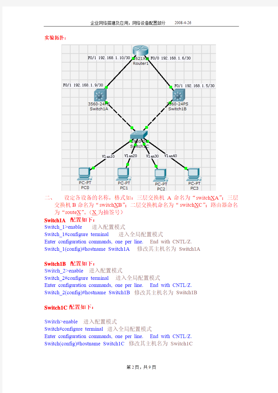
实验拓扑:
二、设定各设备的名称,格式如:三层交换机A命名为“switchXA”;三层
交换机B命名为“switchXB”;二层交换机命名为“switchXC”;路由器命名为“routeX”。(X为抽签号)
Switch1A 配置如下:
Switch_1>enable 进入配置模式
Switch_1#configure terminal 进入全局配置模式
Enter configuration commands, one per line. End with CNTL/Z.
Switch_1(config)#hostname Switch1A 修改其主机名为Switch1A
Switch1B 配置如下:
Switch_2>enable进入配置模式
Switch_2#configure terminal 进入全局配置模式
Enter configuration commands, one per line. End with CNTL/Z.
Switch_2(config)#hostname Switch1B 修改其主机名为Switch1B
Switch1C配置如下:
Switch>enable进入配置模式
Switch#configure terminal 进入全局配置模式
Enter configuration commands, one per line. End with CNTL/Z.
Switch(config)#hostname Switch1C 修改其主机名为Switch1C
Router1配置如下:
Router_1>enable 进入配置模式
Router_1#configure terminal 进入全局配置模式
Enter configuration commands, one per line. End with CNTL/Z.
Router_1(config)#hostname Router1 修改其主机名为Router1
三、在交换机二层交换机上划分VLAN,并加入相应端口(10分)
VLAN 端口
VLAN10 Fa0/1~Fa0/4
VLAN20 Fa0/5~Fa0/9
VLAN30 Fa0/10~Fa0/14
VLAN40 Fa0/15~Fa0/21
Switch1C配置如下:
Switch1C>enable进入配置模式
Switch1C#configure terminal 进入全局配置模式
Enter configuration commands, one per line. End with CNTL/Z.
Switch1C(config)#vlan 10 创建Vlan10
Switch1C(config-vlan)#exit 退出
Switch1C(config)#vlan 20 创建Vlan20
Switch1C(config-vlan)#exit 退出
Switch1C(config)#vlan 30 创建Vlan30
Switch1C(config-vlan)#exit 退出
Switch1C(config)#vlan 40 创建Vlan40
Switch1C(config-vlan)#exit 退出
Switch1C(config)#interface range f0/1-4 进入端口组F0/1-4
Switch1C(config-if-range)#switchport access vlan 10 把其划入到Vlan10中Switch1C(config-if-range)#exit 退出
Switch1C(config)#interface range f0/5-9 进入端口组F0/5-9
Switch1C(config-if-range)#switchport access vlan 20 把其划入到Vlan20中Switch1C(config-if-range)#exit 退出
Switch1C(config)#interface range f0/10-14 进入端口组F0/10-14
Switch1C(config-if-range)#switchport access vlan 30 把其划入到Vlan30中Switch1C(config-if-range)#exit 退出
Switch1C(config)#interface range f0/15-21 进入端口组F0/15-21
Switch1C(config-if-range)#switchport access vlan 40把其划入到Vlan40中
四、在三层交换机上分别配置VLAN的接口IP地址(20分)
交换机名称接口ip
三层交换机A VLAN10 172.16. X.33/27 VLAN20 172.16. X.65/27 VLAN30 172.16. X.97/27 VLAN40 172.16. X.129/27 绑定Fa0/1 192.168. X.9/30
三层交换机B VLAN10 172.16. X.34/27 VLAN20 172.16. X.66/27 VLAN30 172.16. X.98/27 VLAN40 172.16. X.130/27 绑定Fa0/1 192.168. X.5/30
Switch1A配置如下:
Switch1A>enable进入配置模式
Switch1A#configure terminal 进入全局配置模式
Enter configuration commands, one per line. End with CNTL/Z.
Switch1A(config)#interface vlan 10进入Vlan10
Switch1A(config-if)#ip address 172.16.1.33 255.255.255.224 设置其IP地址Switch1A(config-if)#exit 退出
Switch1A(config)#interface vlan 20 进入Vlan20
Switch1A(config-if)#ip address 172.16.1.65 255.255.255.224 设置其IP地址Switch1A(config-if)#exit 退出
Switch1A(config)#interface vlan 30 进入Vlan30
Switch1A(config-if)#ip address 172.16.1.97 255.255.255.224 设置其IP地址Switch1A(config-if)#exit 退出
Switch1A(config)#interface vlan 40进入Vlan40
Switch1A(config-if)#ip address 172.16.1.129 255.255.255.224 设置其IP地址Switch1A(config-if)#exit 退出
Switch1A(config)#interface f0/1 进入端口F0/1
Switch1A(config-if)#ip address 192.168.1.9 255.255.255.252 设置其IP地址
五、在路由器上配置接口IP地址(6分)
接口IP
Fa0/1 192.168. X.10/30
Fa0/0 192.168. X.6/30
Router1配置如下:
Router1>enable 进入配置模式
Router1#configure terminal 进入全局配置模式
Enter configuration commands, one per line. End with CNTL/Z.
Router1(config)#interface f0/1 进入端口F0/1
Router1(config-if)#ip address 192.168.1.10 255.255.255.252 配置其IP地址
Router1(config-if)#no shutdown 激活
Router1(config-if)#exit 退出
Router1(config)#interface f0/0进入端口F0/0
Router1(config-if)#ip address 192.168.1.6 255.255.255.252 配置其IP地址
Router1(config-if)#no shutdown 激活
六、交换路由配置(64分)
a)在全部交换机上配置MSTP协议,并且创建二个MSTP实例:Instance1、
Instance2;其中,Instance1包括:VLAN10、VLAN20;而Instance2包
括:VLAN30、VLAN40;
Switch1A配置如下:
Switch1A>enable 进入配置模式
Switch1A#configure terminal 进入全局配置模式
Enter configuration commands, one per line. End with CNTL/Z.
Switch1A(config)#spanning-tree mst configuration 进入MSTP配置模式
Switch1A(config-mst)#instance 1 vlan 10,20 配置实例1并关联Vlan10,20 Switch1A(config-mst)#instance 2 vlan 30,40 配置实例2并关联Vlan30,40 Switch1A(config-mst)#name wjxz 配置域名为wjxz
Switch1A(config-mst)#revision 1 配置版本(修订号)
Switch1B配置如下:
Switch1B>enable 进入配置模式
Switch1B#configure terminal 进入全局配置模式
Enter configuration commands, one per line. End with CNTL/Z.
Switch1B(config)#spanning-tree mst configuration 进入MSTP配置模式
Switch1B(config-mst)#instance 1 vlan 10,20 配置实例1并关联Vlan10,20 Switch1B(config-mst)#instance 2 vlan 30,40 配置实例2并关联Vlan30,40 Switch1B(config-mst)#name wjxz 配置域名为wjxz
Switch1B(config-mst)#revision 1 配置版本(修订号)
Switch1C配置如下:
Switch1C>enable 进入配置模式
Switch1C#configure terminal进入全局配置模式
Enter configuration commands, one per line. End with CNTL/Z.
Switch1C(config)#spanning-tree mst configuration 进入MSTP配置模式
Switch1C(config-mst)#instance 1 vlan 10,20 配置实例1并关联Vlan10,20 Switch1C(config-mst)#instance 2 vlan 30,40 配置实例2并关联Vlan30,40 Switch1C(config-mst)#name wjxz 配置域名为wjxz
Switch1C(config-mst)#revision 1 配置版本号(修订号)
b)设置MSTP的优先级,实现在Instance1中三层交换机-A为根交换机,
在Instance2中三层交换机-B为根交换机;
Switch1A 配置如下:
Switch1A>enable 进入配置模式
Switch1A#configure terminal 进入全局配置模式
Enter configuration commands, one per line. End with CNTL/Z.
Switch1A(config)#spanning-tree mst 1 priority 4096 配置交换机Switch1A在实例1中的优先级为4096 缺省值是32768 值越小优先成为该wjxz(域)中的root switch
Switch1B配置如下:
Switch1B>enable 进入配置模式
Switch1B#configure terminal 进入全局配置模式
Enter configuration commands, one per line. End with CNTL/Z.
Switch1B(config)#spanning-tree mst 2 priority 4096 配置交换机Switch1B在实例2中的优先级为4096 缺省值是32768 值越小优先成为该wjxz(域)中的root switch
c)配置VRRP组1和VRRP组2,实现VLAN10、VLAN20通过三层交换
机-A转发数据,VLAN30、VLAN40通过三层交换机-B转发数据;Switch1A配置如下:
Switch1A>enable 进入配置模式
Switch1A#configure terminal 进入全局配置模式
Enter configuration commands, one per line. End with CNTL/Z.
Switch1A(config)#interface vlan 10 进入Vlan10
Switch1A(config-if)#vrrp 1 priority 200设置优先级,默认100,优先级高的成为主Switch1A(config-if)#vrrp 1 ip 192.168.1.63 配置虚拟网关
Switch1A(config-if)#vrrp 1 preempt 配置抢占
Switch1A(config-if)#exit 退出
Switch1A(config)#interface vlan 20 进入Vlan20
Switch1A(config-if)#vrrp 1 priority 200 设置优先级,默认100,优先级高的成为主Switch1A(config-if)#vrrp 1 ip 192.168.1.93 配置虚拟网关
Switch1A(config-if)#vrrp 1 preempt 配置抢占
Switch1A(config-if)#exit 退出
Switch1A(config)#interface vlan 30 进入Vlan30
Switch1A(config-if)#vrrp 2 ip 192.168.1.128 配置虚拟网关
Switch1A(config-if)#vrrp 2 priority 80配置优先级,默认100,优先级高的成为主Switch1A(config-if)#vrrp 2 preempt 配置抢占
Switch1A(config-if)#exit 退出
Switch1A(config)#interface vlan 40 进入Vlan40
Switch1A(config-if)#vrrp 2 ip 192.168.1.159 配置虚拟网关
Switch1A(config-if)#vrrp 2 preempt 配置抢占
Switch1A(config-if)#vrrp 2 priority 80配置优先级,默认100,优先级高的成为主Switc1B配置如下:
Switch1B>enable 进入配置模式
Switch1B#configure terminal 进入全局配置模式
Enter configuration commands, one per line. End with CNTL/Z.
Switch1B(config)#interface vlan 10 进入Vlan10
Switch1B(config-if)#vrrp 1 ip 192.168.1.63 配置虚拟网关
Switch1B(config-if)#vrrp 1 priority 80 配置优先级,默认100,优先级高的成为主Switch1B(config-if)#vrrp 1 preempt 配置抢占
Switch1B(config-if)#exit 退出
Switch1B(config)#interface vlan 20 进入Vlan20
Switch1B(config-if)#vrrp 1 priority 80 配置优先级,默认100,优先级高的成为主Switch1B(config-if)#vrrp 1 ip 192.168.1.93 配置虚拟网关
Switch1B(config-if)#vrrp 1 preempt 配置抢占
Switch1B(config-if)#exit 退出
Switch1B(config)#interface vlan 30 进入Vlan30
Switch1B(config-if)#vrrp 2 ip 192.168.1.128 配置虚拟网关
Switch1B(config-if)#vrrp 2 priority 200 配置优先级,默认100,优先级高的成为主Switch1B(config-if)#vrrp 2 preempt 配置抢占
Switch1B(config-if)#exit 退出
Switch1B(config)#interface vlan 40 进入Vlan40
Switch1B(config-if)#vrrp 2 ip 192.168.1.159 配置虚拟网关
Switch1B(config-if)#vrrp 2 preempt 配置抢占
Switch1B(config-if)#vrrp 2 priority 200配置优先级,默认100,优先级高的成为主
d)使用动态路由协议OSPF实现全网互通。
Switch1A 配置如下:
Switch1A>enable 进入配置模式
Switch1A#configure terminal 进入全局配置模式
Enter configuration commands, one per line. End with CNTL/Z.
Switch1A(config)#router ospf 1 进入ospf组1
Switch1A(config-router)#network 192.168.1.8 0.0.0.3 area 0 宣告直连网段Switch1A(config-router)#network 192.168.1.32 0.0.0.31 area 0
Switch1A(config-router)#network 192.168.1.64 0.0.0.31 area 0
Switch1A(config-router)#network 192.168.1.128 0.0.0.31 area 0
Switch1A(config-router)#network 192.168.1.96 0.0.0.31 area 0
Switch1B配置如下:
Switch1B>enable 进入配置模式
Switch1B#configure terminal 进入全局配置模式
Enter configuration commands, one per line. End with CNTL/Z.
Switch1B(config)#router ospf 1 进入ospf组1
Switch1B(config-router)#network 192.168.1.4 0.0.0.3 area 0宣告直连网段Switch1B(config-router)#network 192.168.1.96 0.0.0.31 area 0
Switch1B(config-router)#network 192.168.1.128 0.0.0.31 area 0
Switch1B(config-router)#network 192.168.1.64 0.0.0.31 area 0
Switch1B(config-router)#network 192.168.1.32 0.0.0.31 area 0
Router1配置如下:
Router1>enable 进入配置模式
Router1#configure terminal 进入全局配置模式
Enter configuration commands, one per line. End with CNTL/Z.
Router1(config)#router ospf 1 进入ospf组1
Router1(config-router)#network 192.168.1.8 0.0.0.3 area 0 宣告直连网段Router1(config-router)#network 192.168.1.4 0.0.0.3 area 0
e)禁用MSN的访问接口。设MSN服务器设置如下。UDP方式:
169.89.75.201、8000端口;TCP方式:169.89.70.98、443端口Router1配置如下:
Router1>enable 进入配置模式
Router1#configure terminal 进入全局配置模式
Enter configuration commands, one per line. End with CNTL/Z.
Router1(config)#access-list 100 deny udp 169.89.75.201 0.0.0.0 any eq 8000 配置扩展访问列表
Router1(config)#access-list 100 deny tcp 169.89.70.97 0.0.0.0 any eq 443
配置扩展访问列表
f)完成所有配置后,分别将各设备的当前配置文件在捕获生成txt格式。以
第二题中的设备名称保存在距离交换机最近的PC桌面中。