NFF0151331BP-XC中文资料
Volant NCA015 Series Non-Isolated 15A SIP/SMT DC/DC Converters
Features:
9Small size, minimal footprint – SMT/SIP package 915A Output Current (all voltages)
9High Efficiency: up to 96%
9High reliability
9RoHS Compliant
9Cost efficient open frame design
9Output voltage programmable by an external resistor 9Monotonic Start with Pre-Bias
9Over-current and Over-temperature protection Output
Input
Efficiency
PARD (mVp-p) Regulation
Max
Vin
Nom.
(V)
Range
(V)
Iin
Max
(A)
Full Load
Vout (V) Iout
(A)
Typ. Max. Line Load Typ.
1 15 28 50
+/-0.2%
+/-0.4% 5 3
–5.5 5.81 82% 1.2 15 28 50 +/-0.2%
+/-0.4% 5 3
–5.5 6.89 84% 1.5 15 28 50 +/-0.2%
+/-0.4% 5 3
–5.5 8.42 87% 1.8 15 28 50 +/-0.2%
+/-0.4% 5 3
–5.5 9.89 88% 2 15 28 50
+/-0.2%
+/-0.4% 5 3
–5.5
10.86 89% 2.5 15 28 50 +/-0.2%
+/-0.4% 5 3
–5.5 11.5 92% 3.3 15 28 50 +/-0.2%
+/-0.4% 5 4.5-5.5 11.45 94%
Volant NCA015 Series
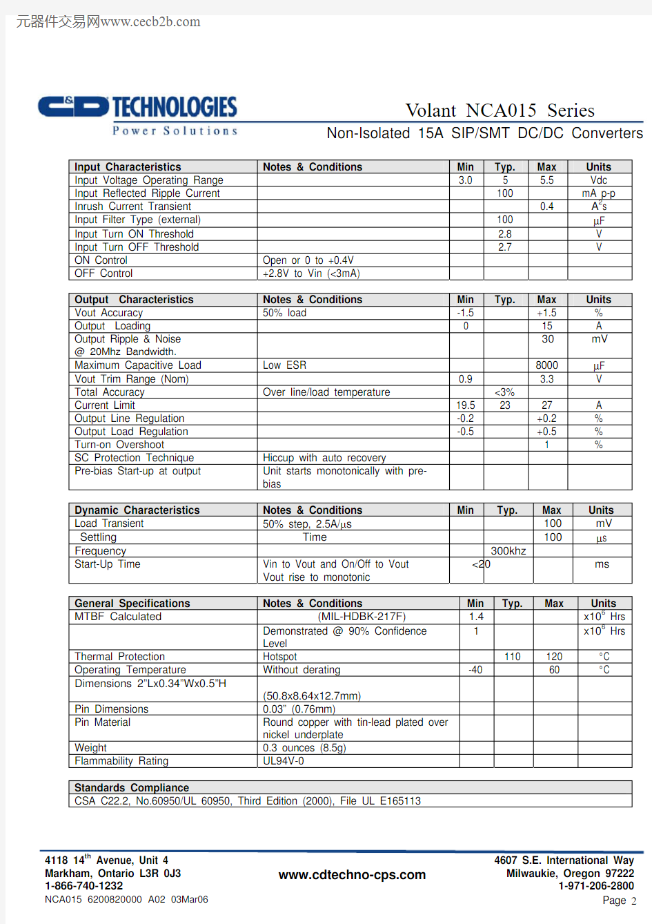
Non-Isolated 15A SIP/SMT DC/DC Converters Input Characteristics Notes & Conditions Min Typ. Max Units
Input Voltage Operating Range 3.0 5 5.5 Vdc
Input Reflected Ripple Current 100 mA p-p Inrush Current Transient 0.4 A2s
Input Filter Type (external) 100 μF
Input Turn ON Threshold 2.8 V
Input Turn OFF Threshold 2.7 V
ON Control Open or 0 to +0.4V
OFF Control +2.8V to Vin (<3mA)
Output Characteristics Notes & Conditions Min Typ. Max Units
Vout Accuracy 50% load -1.5 +1.5 %
Output Loading 0 15 A
Output Ripple & Noise @ 20Mhz Bandwidth. 30
mV
Maximum Capacitive Load Low ESR 8000 μF
Vout Trim Range (Nom) 0.9 3.3 V
Total Accuracy Over line/load temperature <3%
Current Limit 19.5 23 27 A
Output Line Regulation -0.2 +0.2 %
Output Load Regulation -0.5 +0.5 %
Turn-on Overshoot 1 %
SC Protection Technique Hiccup with auto recovery
Pre-bias Start-up at output Unit starts monotonically with pre-
bias
Dynamic Characteristics Notes & Conditions Min Typ. Max Units
Load Transient 50% step, 2.5A/μs100 mV
Settling
Time 100
μs
Frequency 300khz
Start-Up Time Vin to Vout and On/Off to Vout
Vout rise to monotonic
<20 ms
General Specifications Notes & Conditions Min Typ. Max Units
MTBF Calculated
(MIL-HDBK-217F)
1.4
x106 Hrs
Demonstrated @ 90% Confidence
Level
1 x10⁶ Hrs
Thermal Protection Hotspot 110 120 °C
Operating Temperature Without derating -40 60 °C
Dimensions 2”Lx0.34”Wx0.5”H
(50.8x8.64x12.7mm)
Pin Dimensions 0.03” (0.76mm)
Pin Material Round copper with tin-lead plated over
nickel underplate
Weight 0.3 ounces (8.5g)
Flammability Rating UL94V-0
Standards Compliance
CSA C22.2, No.60950/UL 60950, Third Edition (2000), File UL E165113
Volant NCA015 Series
Non-Isolated 15A SIP/SMT DC/DC Converters
Thermal Considerations
The power module operates in a variety of thermal environments; however, sufficient cooling should be provided to help ensure reliable operation of the unit.
The thermal data presented is based on measurements taken at various airflows. Note that airflow is parallel to the long axis of the module as shown in Figure 1 and derating applies accordingly.
Figure 1. Thermal Tests Set-Up.
The temperature at either location should not exceed 110oC. The output power of the module should not exceed the rated power for the module(Vo,set X Io,max).
Convection Requirements for Cooling
To predict the approximate cooling needed for the module, refer to the Power Derating Curves in Figures 2-15 .
These derating curve are approximations of the ambient temperature and airflow required to keep the power module temperature below it's maximum rating. Once the module is assembled in the actual system, the module's temperature should be verified.
Volant NCA015 Series
Non-Isolated 15A SIP/SMT DC/DC Converters TYPICAL DERATING CURVES SIP/SMT VERSION
Fig. 2. SMT Power Derating vs Output Current for 5Vin 3.3V Out.
Fig. 3. SIP Power Derating vs Output Current for 5Vin 3.3V Out.
Volant NCA015 Series
Non-Isolated 15A SIP/SMT DC/DC Converters
Fig 4. SMT Power Derating vs Output Current for 5Vin 2.5V Out.
Fig 5. SIP Power Derating vs Output Current for 5Vin 2.5V Out.
Volant NCA015 Series
Non-Isolated 15A SIP/SMT DC/DC Converters
Fig 6. SMT Power Derating vs Output Current for 5Vin 2.0V Out.
Fig 7. SIP Power Derating vs Output Current for 5Vin 2.0V Out.
Volant NCA015 Series
Fig 8. SMT Power Derating vs Output Current for 5Vin 1.8V Out.
Fig 9. SIP Power Derating vs Output Current for 5Vin 1.8V Out.
Volant NCA015 Series
Non-Isolated 15A SIP/SMT DC/DC Converters
Fig 10. SMT Power Derating vs Output Current for 5Vin 1.5V Out.
Fig 11. SIP Power Derating vs Output Current for 5Vin 1.5V Out.
Volant NCA015 Series
Fig 12. SMT Power Derating vs Output Current for 5Vin 1.2V Out.
Fig 13. SIP Power Derating vs Output Current for 5Vin 1.2V Out.
Volant NCA015 Series
Fig. 14. SMT Power Derating vs Output Current for 5Vin 1.0V Out.
Fig 15. SIP Power Derating vs Output Current for 5Vin 1.0V Out.
Volant NCA015 Series
Non-Isolated 15A SIP/SMT DC/DC Converters TYPICAL EFFICIENCY CURVES FOR VARIOUS VOLTAGE MODELS SIP/SMT VERSION.
Fig 16. SMT Efficiency Curves for Vout=3.3V (25C)
Fig 17. SIP Efficiency Curves for Vout=3.3V (25C)
Volant NCA015 Series
Fig 18. SMT Efficiency Curves for Vout=2.5V (25C)
Fig 19. SIP Efficiency Curves for Vout=2.5V (25C)
Volant NCA015 Series Non-Isolated 15A SIP/SMT DC/DC Converters
Fig 20. SMT Efficiency Curves for Vout=2.0V (25C)
Fig 21. SIP Efficiency Curves for Vout=2.0V (25C)
Volant NCA015 Series
Fig 22. SMT Efficiency Curves for Vout=1.8V (25C)
Fig 23. SIP Efficiency Curves for Vout=1.8V (25C)
Volant NCA015 Series
Fig 24. SMT Efficiency Curves for Vout=1.5V (25C)
Fig 25. SIP Efficiency Curves for Vout=1.5V (25C)
Volant NCA015 Series
Fig 26. SMT Efficiency Curves for Vout=1.2V (25C)
Fig 27. SIP Efficiency Curves for Vout=1.2V (25C)
Volant NCA015 Series
Fig 28. SMT Efficiency Curves for Vout=1.0V (25C)
Fig 29. SIP Efficiency Curves for Vout=1.0V (25C)
Volant NCA015 Series
Non-Isolated 15A SIP/SMT DC/DC Converters Typical Start Up
Ch 1. Enable
Ch2. Vout, Full load.
Ch3. Q1-Vgs
Ch4. Q2-Vgs
Typical Start Up with pre-bias
Ch1 : Enable
Ch2 : Vout
Ch3 : Output current at No Load.
Volant NCA015 Series
Non-Isolated 15A SIP/SMT DC/DC Converters
Typical Output Noise and Ripple
Output Voltage Set point adjustment.
The following relationship establish the calculation of external resistors:
51107525
.021070??=Vo R adj
For Vout setting an external resistor is connected between the TRIM and Ground Pin.
Resistor values for different output voltages are calculated as given in the table:
Vo, set (Volts)
RAdj (K Ω)
3.3 3.160
2.5 6.947 2.0 11.780 1.8 15.004 1.5 2
3.077 1.2 41.973 1.0 80.02 0.9 137.74 0.75 Open
Remote Sense:
All C&D SMT/SIP power modules offer an option for remote sense. The remote sense compensates for any distribution drops to accurately control voltage at the point of load. The voltage between the sense pin to Vout pin should not exceed 0.5V.
Volant NCA015 Series
Non-Isolated 15A SIP/SMT DC/DC Converters SMT Lead free Reflow profile
1. Ramp up rate during preheat : 1.33 ℃/Sec ( From 30℃ to 150℃ )
2. Soaking temperature : 0.29 ℃/Sec ( From 150℃ to 180℃ )
3. Ramp up rate during reflow : 0.8 ℃/Sec ( From 220℃ to 250℃ )
4. Peak temperature : 250℃, above 220℃ 40 to 70 Seconds
5. Ramp up rate during cooling : -1.56 ℃/Sec ( From 220℃ to 150℃ )