Synthesis and size control of monodisperse copper nanoparticles

Journal of Colloid and Interface Science311(2007)
417–424
https://www.wendangku.net/doc/f614791273.html,/locate/jcis
Synthesis and size control of monodisperse copper nanoparticles
by polyol method
Bong Kyun Park a,Sunho Jeong a,Dongjo Kim a,Jooho Moon a,?,Soonkwon Lim b,Jang Sub Kim b
a Department of Materials Science and Engineering,Yonsei University,Seoul120-749,South Korea
b LCD R&D Center,Samsung Electronics Co.Ltd.,Gyeonggi-Do449-711,South Korea
Received25November2006;accepted17March2007
Available online24March2007
Abstract
We describe herein the synthesis of metallic copper nanoparticles in the presence of poly(vinylpyrrolidone),employed as a protecting agent,via a polyol method in ambient atmosphere.The obtained copper particles were con?rmed by XRD to be crystalline copper with a face-centered cubic (fcc)structure.We observed monodisperse spherical copper nanoparticles with a diameter range45±8nm.The particle size and its distribution are controlled by varying the synthesis parameters such as the reducing agent concentration,reaction temperature,and precursor injection rate.The precursor injection rate plays an important role in controlling the size of the copper nanoparticles.On the basis of XPS and HRTEM results,we demonstrate that the surface of the copper is surrounded by amorphous CuO and that poly(vinylpyrrolidone)is chemisorbed on the copper surface.?2007Elsevier Inc.All rights reserved.
Keywords:Cu nanoparticles;Polyol synthesis;Particle size control;Surface characterization;Conductive ink
1.Introduction
During the last two decades,a substantial body of research has been directed toward the synthesis of metal nanoparticles in efforts to explore their special properties and potential applica-tions[1–4].Among various metal particles,copper nanoparti-cles have attracted considerable attention because of their cat-alytic,optical,and electrical conducting properties[5–8].Cop-per nanoparticles are particularly attractive for application in printed circuit boards(PCBs)and?exible electronics.
Metal nanopowders can be used as a key constituent for preparing the paste or ink from which conductive tracks are patterned by either screen printing or ink-jet printing.The melt-ing point(T m)of nanomaterials can be dramatically lowered by decreasing the size of the material relative to their bulk coun-terparts[9].This low temperature melting ability makes metal nanopowders potentially suitable materials for use in printed electronics,since they can be annealed at lower temperatures to form conductive?lms of low resistance.
*Corresponding author.Fax:+8223655882.
E-mail address:jmoon@yonsei.ac.kr(J.Moon).
Currently,mainly noble metals such as gold and silver are being exploited,despite their costliness.In this regard,cop-per is a good alternative material as it is highly conductive and much more economical than Au and Ag.Several methods have been developed for the preparation of copper nanoparticles,in-cluding thermal reduction[5],sono-chemical reduction[5,10], metal vapor synthesis[6],chemical reduction[7],vacuum va-por deposition[8],radiation methods[11],microemulsion tech-niques[12–14],and laser ablation[15].
Most of the aforementioned methods utilize an oxygen-free environment to synthesize copper as it readily oxidizes in air. Lisiecki et al.[16]prepared copper nanoparticles in an aqueous solution using sodium dodecyl sulfate as capping molecules. They employed a glove box to prevent oxidation of the par-ticles.Joshi et al.and Wu et al.independently reported the synthesis of copper nanoparticles in an aqueous system un-der a nitrogen atmosphere[10,17].Unlike to other techniques, in the present study,we have developed a polyol method for the preparation of highly monodisperse copper nanoparticles in https://www.wendangku.net/doc/f614791273.html,e of nonaqueous solvent as a reaction medium al-lows us to minimize the copper surface oxidation.Furthermore, poly(vinylpyrrolidone)added as a dispersing agent also effec-tively prevents the oxidation process.A key advantage of polyol
0021-9797/$–see front matter?2007Elsevier Inc.All rights reserved. doi:10.1016/j.jcis.2007.03.039
418 B.K.Park et al./Journal of Colloid and Interface Science 311(2007)
417–424
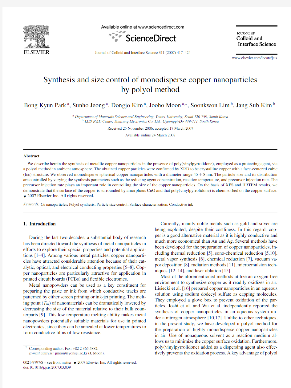
Fig.1.SEM images and particle size distribution of synthesized copper particles as a function of the amount of reducing agent:(a)12.75mmol (sample #1);(b)17.53mmol (sample #2);and (c)19.13mmol (sample #3).Scale bar =100nm.The arrows represent an impurity phase.
process-based nanoparticle synthesis is that the reaction kinet-ics can be easily controlled,as demonstrated by Fievet et al.[18–21].We have controlled the size and size distribution of the particles by varying experimental parameters such as the amount of reducing agent,reaction temperature,and precursor injection rate.2.Experimental
2.1.Preparation of copper particles
Poly(N -vinylpyrrolidone)(PVP,M w =40,000,Sigma–Aldrich),acting as a capping molecule,was dissolved in di-ethyleneglycol (DEG,99%,Sigma–Aldrich).Sodium phosphi-nate monohydrate (NaH 2·PO 2·H 2O,Junsei),used as a reducing agent,was added to the DEG solution and the solution was heated to reaction temperatures.The aqueous solution of cop-per(II)sulfate pentahydrate (98%,Sigma–Aldrich)was then injected into the hot reaction medium via a syringe pump.
The injection rate of the Cu salt solution was varied from 2to 8ml /min.After 1h of reaction,the solution was cooled to room temperature and the particles were separated by centrifu-gation and then washed with methanol.The detailed reaction conditions employed in the particle synthesis are summarized in Table 1.
2.2.Characterization
Phase composition and crystallinity of the synthesized cop-per particles were investigated using an X-ray diffractome-ter (XRD,DMAX2500,Rigaku)employing Cu Kα1radiation (1.51059?).The morphology of the copper particles was inves-tigated via scanning electron microscopy (SEM,JSM-6500F,JEOL)and the particle size distributions were obtained by im-age analysis.The surface compositions of the copper particles were investigated by X-ray photoelectron spectroscopy (XPS,ESCALAB 22i-XL,VG Scienti?c Instrument)and the sur-
B.K.Park et al./Journal of Colloid and Interface Science311(2007)417–424419 Table1
Synthesis conditions for the preparation of copper particles using the injection
method
Sample ID Reducing agent
(mmol)Reaction temperature
(?C)
Injection rate
(ml/min)
Cu salt
(mmol)
#112.75200220
#217.53200220
#319.13200220
#417.53200820
#517.53170820
#617.53140820
#717.53200620
#817.53140280
#917.53140680
#1017.53140880 face morphology was examined by high resolution transmission
electron microscopy(HRTEM,JEM-4010,JEOL).
3.Results and discussion
3.1.In?uence of reducing agent
In a typical polyol process,a polyol liquid such as di-
ethyleneglycol acts not only as a reaction medium but also as
a reducing agent.However,in the case of copper nanoparticle
synthesis,the reducing ability of diethyleneglycol is insuf?cient
to reduce the copper ions because copper is easily oxidized
to either CuO or Cu2O in air atmosphere[22].We introduce
NaH2PO2·H2O as a reducing agent.NaH2PO2·H2O is gener-ally used in aqueous chemical reduction for the preparation of
copper particles.It produces oxidation reaction represented by
the equation
H2PO?2+H2O→H2PO?3+2H++2e?,(1) in an acidic condition,releasing electrons.The released elec-trons are utilized to reduce copper ions as shown in the equation Cu2++2e?→Cu.(2) According to the equations,the rate and amount of the electrons supplied to the copper ions are determined by sodium phosphi-nate.In this study,we control the synthesis reaction kinetics by adjusting the amount of the reduction agent.
Fig.1shows SEM images of particles synthesized with vary-
ing amounts of reducing agent.At low reducing agent concen-
tration(12.75mmol),the reducing rate of the copper precursor
is sluggish and consequently only a few nuclei are formed at
the nucleation step.Precipitating copper atoms at the later pe-
riod of the reaction are mostly involved in particle growth by
collision with already generated nuclei rather than in the for-
mation of new particles.This reaction mechanism leads to the
formation of larger sized particles,as shown in Fig.1a.With
increasing reducing agent concentration,the enhanced reduc-
tion rate favors the generation of more nuclei,resulting in the
formation of smaller copper particles(Fig.1b).At a higher
reduction rate(19.13mmol),the number of precipitating metal-
lic clusters steeply increases and considerably more nuclei are
produced during a single event of the nucleation period.Even-
tually,the size of particles decreases because the amount
of Fig.2.Schematic illustration of nucleation and growth mechanisms based on LaMer’s model:(a)mechanism for polydisperse particles and(b)mechanism for monodisperse particles.
solute available for particle growth per growing particle de-creases with the increasing number of nuclei.The reaction at higher reducing agent concentration also leads to the forma-tion of an unidenti?ed impurity phase,as shown in Fig.1c. In a polyol process,the dissolved metal ions are not directly reduced into a neutral metal species,but transformed into an intermediate solid phase comprised of hydroxyethyleneglyco-late or corresponding alkoxide radicals prior to nucleation step. Then,the re-dissolved metal ion from the intermediate solid phase is consumed in nucleation and growth processes[23,24]. In this regard,it is considered that the intermediate solid phase itself is reduced in the presence of extremely high reducing agent,forming unidenti?ed impurity phase.
The particle characteristics of the synthesized copper are de-termined by the nucleation and growth mechanisms.When the reduction rate of copper ions exceeds the consumption rate of copper clusters by particle growth,the concentration of reduced copper atoms(C)likely remains over a critical supersatura-tion level(C crit)for longer time or?uctuates around C crit.This allows an extended nucleation period or multiple nucleation events and,in turn,the growing period of each nucleus will dif-fer(Fig.2a).Therefore,the?nal particles exhibit broader size compared to that of particles grown at the same rate after a sin-gle nucleation event(Fig.2b).
420 B.K.Park et al./Journal of Colloid and Interface Science 311(2007)
417–424
Fig.3.SEM images and particle size distribution of synthesized copper particles as a function of the reaction temperature:(a)200?C (sample #4);(b)170?C (sample #5);and (c)140?C (sample #6).Scale bar =100nm.
3.2.In?uence of reacting temperature
Fig.3shows SEM images of copper particles synthesized at different temperatures.With decreasing reaction tempera-ture,the size of the resulting particles becomes smaller and the size distribution is also narrowed.At 200?C,the obtained particle size was 53±13nm (Fig.3a),whereas that at the syn-thesis temperature of 140?C was 45±8nm (Fig.3c).When copper salt solution is injected into a reaction medium main-tained at 200?C,the color of the medium in the vicinity where the precursor solution is added changes from light yellow to dark red.This indicates that copper particles are rapidly gener-ated when the precursor solution is injected.A high reducing rate at the temperature of 200?C allows instantaneous multi-ple nucleations to occur when the precursor solution is added dropwise.The resulting particles at this condition exhibit a rel-atively broad size distribution due to uneven particle growth and coagulation of the primary particles.
In contrast to the reaction at 170and 200?C,the color of the reaction medium changes to light blue rather than dark red when the precursor solution is injected at 140?C.The aque-ous solution of copper ions has a blue color.This indicates that there is no immediate reduction of copper ions upon addition to the reaction medium.After approximately 10s,the solution suddenly turns dark red,indicating nucleation.If the number of nuclei is large enough to lower the concentration of copper atoms below the critical supersaturation level,no further nucle-ation occurs and the nucleated particles continue to grow.Coag-ulation of the primary particles would be unlikely because the thermal energy is not suf?cient for vigorous particle movement.Under these nucleation and growth conditions,as depicted in Fig.2b,the resulting particles are relatively monodisperse.At
B.K.Park et al./Journal of Colloid and Interface Science311(2007)417–424
421
Fig.4.SEM images and particle size distribution of copper particles synthesized at200?C as a function of the precursor injection rate:(a)2ml/min(sample#2);
(b)6ml/min(sample#7);and(c)8ml/min(sample#4).Scale bar=100nm.
temperature lower than140?C,however,the reaction medium remains light blue in color,implying that the copper ions do not undergo reduction to copper atoms.
3.3.In?uence of injection rate
We also controlled the injection rate of the copper salt pre-cursor to the PVP dissolved polyol medium.Fig.4shows SEM images of particles with synthesized different precursor injec-tion rates at200?C.The particles become smaller and nar-rower as the injection rate is increased.At an injection rate of 2ml/min,the obtained particle size was63±17nm(Fig.4a), whereas that at8ml/min was47±14nm(Fig.4c).The in-jection rate determines the amount of copper ions per unit time to be reduced.When the reduction rate is high enough to re-duce copper ions as soon as they are supplied,the precursor injection rate will be equal to the production rate of copper atoms.The concentration of copper atoms slowly reaches C crit at slow injection of the precursor.The nucleation rate is slug-gish and the number of nuclei is small.Therefore,the resulting particles are large and broad.In contrast,fast injection of the precursor results in a steep increase in the concentration of cop-per atoms,permitting a short burst of nucleation and generating many nuclei.This leads to smaller particles with better mono-dispersity.
The in?uence of the precursor injection rate varies depend-ing upon the reaction temperature.Fig.5shows SEM images of particles synthesized with different precursor injection rates at140?C.Contrary to the previous results,the particles tend to become larger and broader as the injection rate is increased.At 2ml/min,the obtained particle size was60±10nm(Fig.5a) whereas that at8ml/min was68±20nm(Fig.5c).If the reac-
422 B.K.Park et al./Journal of Colloid and Interface Science 311(2007)417–424
Fig.5.SEM images and particle size distribution of copper particles synthesized at 140?C as a function of the precursor injection rate:(a)2ml /min (sample #8);(b)6ml /min (sample #9);and (c)8ml /min (sample #10).Scale bar =100nm.
tion rate is too fast at lower temperature,the generation rate of
copper atoms exceeds the rate of consumption of copper atoms by particle growth and multiple nucleations may occur,result-ing in polydisperse particles.
3.4.Characteristics of copper particles
In addition to particle size and distribution,particle char-acteristics were also investigated.Monodisperse Cu particles (sample #6)were used for the phase and surface composition analyses.The particles synthesized in ambient atmosphere were determined to be phase-pure Cu without any impurity phase such as CuO,Cu 2O,or Cu(OH)2.X-ray diffraction patterns correspond to crystalline copper characteristic peaks with a face-centered-cubic (fcc)crystal structure as shown in Fig.6.The same X-ray diffraction peaks were observed for the sample stored for 30days in ambient condition.
Fig.6.X-ray diffraction pattern of copper particles synthesized at 140?C with an injection rate of 8ml /min (sample #6).
B.K.Park et al./Journal of Colloid and Interface Science311(2007)417–424
423
Fig.7.X-ray photoelectron spectra of Cu nanoparticles:the peaks from(a)Cu 2p3/2,(b)C1s,and(c)O1s.
Surfaces of copper particles are analyzed by X-ray photho-electron spectroscopy(XPS)as shown in Fig.7.We identi?ed a copper peak at932.0eV together with weak CuO peaks at 934.2eV,as shown in Fig.7a[23].The existence of PVP is also con?rmed by XPS spectra of C1s.The C1s spectrum is com-posed of four peaks and the binding energies of these peaks are 284.5eV(C–H bonding),285.3eV(C–C bonding),286.2eV (C–N bonding),and287.9eV(C=O bonding).These binding energies can be attributed to four types of carbon atoms in
PVP.Fig.8.HRTEM image of the synthesized Cu nanoparticles.The inset is the selected area diffraction pattern.
The O1s peak composed of two peaks,one placed at531.2eV
(C=O bonding)and the other placed at533.2eV(C–OH bond-
ing).The O1s peak from the carboxyl(C=O)oxygen atom at
531.2eV shifts to higher binding energy relative to pure PVP,
indicating that the PVP is strongly chemisorbed to the surface
of copper particles[24].This interaction is achieved by coor-
dination bond between Cu ions and PVP molecules,and Cu
ions are surrounded by PVP molecules prior to nucleation step
[25–27].Thus,the chemically adsorbed PVP molecules can
prevent the copper particles from oxidation during the nucle-
ation and growth processes.However,incomplete prevention
from the oxidation takes place.The oxidation has two main
origins.The Cu nanoparticles were synthesized from water con-
taining polyol medium in ambient condition.Some oxygen dis-
solved in the reaction medium results in partial oxidation at the
surface of the Cu nanoparticles.Some oxidation may also occur
when the samples for analysis are prepared in air.
Fig.8shows an HRTEM image of the synthesized Cu par-
ticles.Most of the particles are single crystals,but some con-
tain a twin boundary.The surface of the particle is surrounded
by an amorphous layer with a thickness of~1.5nm.All the
selected area diffraction patterns correspond to face-centered-
cubic structured Cu,showing no crystalline CuO.Based on the
XPS and HRTEM results,it appears that the surface amorphous
layer consists of chemisorbed PVP and amorphous CuO.
4.Conclusions
We have synthesized copper nanoparticles in ambient at-
mosphere by a polyol method.The obtained copper particles
were con?rmed to be phase-pure crystalline copper with face-
centered cubic(fcc)structure on the basis of XRD analyses.
Detailed surface analyses by XPS and HRTEM revealed that
the synthesized particles consist of single crystal Cu surrounded
by amorphous CuO and chemisorbed PVP with a thickness of ~1.5nm.We have adjusted the synthesis parameters to control the size and size distribution of the particles.Particle size de-
creases with increasing reducing agent concentration.The Cu
precursor injection rate plays an important role in controlling
424 B.K.Park et al./Journal of Colloid and Interface Science311(2007)417–424
the particle size,whereas reaction temperature determines the particle size distribution.We obtained relatively monodisperse copper nanoparticles with a size range of45±8nm at optimum conditions.
Acknowledgments
This work was supported by the Korea Science and Engi-neering Foundation(KOSEF)through the National Research Lab.Program funded by the Ministry of Science and Technol-ogy(No.M10500000011).
References
[1]G.G.Ferrier,A.R.Berzins,N.M.Davey,Platinum Metals Rev.29(1985)
175.
[2]J.H.Fendler,Chem.Rev.87(1987)877.
[3]N.Toshima,T.Yonezawa,New J.Chem.22(1998)1179.
[4]M.Brust,C.J.Kiely,Colloids Surf.A202(2002)175.
[5]N.A.Dhas,C.P.Raj,A.Gedanken,Chem.Mater.10(1998)1446.
[6]G.Vitulli,M.Bernini,S.Bertozzi,E.Pitzalis,P.Salvadori,S.Coluccia,
G.Martra,Chem.Mater.14(2002)1183.
[7]H.H.Huang,F.Q.Yan,Y.M.Kek,C.H.Chew,G.Q.Xu,W.Ji,P.S.Oh,
S.H.Tang,Langmuir13(1997)172.
[8]Z.Liu,Y.Bando,Adv.Mater.15(2003)303.
[9]D.Kim,S.Jeong,J.Moon,Nanotechnology17(2006)4019.
[10]R.V.Kumar,Y.Mastai,Y.Diamant,A.Gedanken,J.Mater.Chem.11
(2001)1209.
[11]I.G.Casella,T.R.I.Cataldi,A.Guerrieri,E.Desimoni,Anal.Chim.Acta
335(1996)217.
[12]I.Lisiecki,M.P.Pileni,J.Am.Chem.Soc.115(1993)3887.
[13]M.P.Pileni,B.W.Ninham,T.Gulik-Krzywicki,J.Tanori,I.Lisiecki,
A.Filankembo,Adv.Mater.11(1999)1358.
[14]L.Qi,J.Ma,J.Shen,J.Colloid Interface Sci.186(1997)498.
[15]M.S.Yeh,Y.S.Yang,Y.P.Lee,H.F.Lee,Y.H.Yeh,C.S.Yeh,J.Phys.
Chem.B103(1999)6851.
[16]I.Lisiecki,F.Billoudet,M.P.Pileni,J.Phys.Chem.100(1996)4160.
[17]S.Wu,D.Chen,J.Colloid Interface Sci.273(2004)165.
[18]G.Viau,F.Fievet-Vincent,F.Fievet,Solid State Ionics84(1996)259.
[19]P.Y.Silvert,K.Tekaia-Elhsissen,Solid State Ionics82(1995)53.
[20]F.Fitvet,https://www.wendangku.net/doc/f614791273.html,gier,B.Blin,B.Beaudoin,M.Figlarz,Solid State Ion-
ics32–33(1989)198.
[21]F.Fievet,F.Fievet-Vincent,https://www.wendangku.net/doc/f614791273.html,gier,B.Dumont,M.Figlarz,J.Mater.
Chem.3(1993)627.
[22]R.A.Swalin,Thermodynamics of Solid,second ed.,Wiley,New York,
1972,p.114.
[23]M.Yin,C.K.Wu,K.Lou,C.Burda,J.T.Koberstein,Y.Zhu,S.O’Brien,
J.Am.Chem.Soc.127(2005)9506.
[24]P.Jiang,S.Y.Li,S.S.Xie,Y.Gao,L.Song,Chem.Eur.J.10(2004)4817.
[25]Y.Gao,P.Jiang,D.F.Liu,H.J.Yuan,X.Q.Yan,Z.P.Zhou,J.X.Wang,
L.Song,L.F.Liu,J.M.Zhang,D.Y.Shen,J.Phys.Chem.B108(2004) 12877.
[26]B.Yin,H.Ma,S.Wang,S.Chen,J.Phys.Chem.B107(2003)8898.
[27]I.Washio,Y.Xiong,Y.Yin,Y.Xia,Adv.Mater.18(2006)1745.
系泊系统的设计和探究
赛区评阅编号(由赛区组委会填写): 2016年高教社杯全国大学生数学建模竞赛 承诺书 我们仔细阅读了《全国大学生数学建模竞赛章程》和《全国大学生数学建模竞赛参赛规则》(以下简称为“竞赛章程和参赛规则”,可从全国大学生数学建模竞赛网站下载)。 料 我们的报名参赛队号(12位数字全国统一编号): 参赛学校(完整的学校全称,不含院系名): 参赛队员 (打印并签名) :1. 2.
3. 指导教师或指导教师组负责人 (打印并签名): (指导教师签名意味着对参赛队的行为和论文的真实性负责) 日期:年月日 送全国评阅统一编号(赛区组委会填写): 全国评阅随机编号(全国组委会填写): (请勿改动此页内容和格式。此编号专用页仅供赛区和全国评阅使用,参赛队打印后装订到纸质论文的第二页上。注意电子版论文中不得出现此页。)
系泊系统的设计和探究 摘要 本文利用牛顿力学定律,力矩平衡原理、非线性规划、循环遍历法等方法对系泊系统进行了设计与探究。通过对系泊系统各组件和浮标运用牛顿经典力学体系进行分析,得到了各个情况下的钢桶倾斜角度、锚链状态、浮标吃水深度和游动区域。 ?, 。当风 对于第二问,求解当海面风速为36m/s时,浮标的吃水深度和游动区域、钢桶以及钢管的倾斜角度和锚链形态。利用第一问中的力学方程和程序,求得钢桶的倾角为19.5951?和四节钢管的倾斜角度依次为19.756?、19.755?、19.916?、20.076?。浮标的游动区域为以锚在海面上的投影为圆心,半径为18.8828m的圆。由于部分数据与问题二中钢桶的倾斜角度不超过5?,锚链在锚点与海床的夹角不超过16?的要求不符,所以通过调节重物球的质量使钢桶的倾斜角度和锚链在锚点与海床的夹角处在要求的范围之内。借助MATLAB程序中的循环遍历法,可以求得重物球的质量3770kg。
2016数学建模A题系泊系统设计
系泊系统的设计 摘要 对于问题一,建立模型一,已知题目给出的锚链长度与其单位长度的质量,得到悬链共210环。对各节锚链,钢桶,四节钢管受力分析得出静力平衡方程,使用分段外推法,可以得到静力平衡下的迭代方程。其中锚对锚链的拉力大小方向为输入变量,迭代的输出变量为浮标的位置和对钢管的拉力,在给定的风速下,输入和输出满足关系2)2(25.1cos 水v h T -=α,αθcos cos 11T T =,通过多层搜索算法得出最符合的输入输出值,即可得到给定风速下浮标的吃水深度,浮标拉力、锚链与海床夹角。利用MATLAB 软件编程求解模型得到:风力12m/s 时,钢桶与竖直方向上的角度1.9863度,从下往上四节钢管与竖直方向夹角为1.9652度、1.9592度、1.9532度、1.9472度,浮标吃水0.7173m ,以锚为圆心浮标的游动区域16.5125m ,锚链末端切线与海床的夹角3.8268度。风力24m/s 时,锚链形状,钢桶与竖直方向上的夹角3.9835度,从下往上四节钢管与竖直方向夹角为3.9420度、3.9301度、3.9183度、3.9066度,浮标吃水0.7244m ,以锚为圆心浮标的游动区域18.3175m 。锚链末端切线与海床夹角15.9175度。 对于问题二的第一小问,使用模型一求解,当风速36m/s 时,锚链末端切线与海床夹角26.3339度,浮标吃水0.7482m ,浮标游动区域为以锚为圆心半径为18.9578m 的圆形区域,从下往上四节钢管与竖直方向倾斜角度为8.4463度、8.4225度、8.3989度、8.3753度,钢桶与竖直方向倾斜角度为8.5294度。为满足问题二的要求,在模型一的基础上把重物球质量作为变量,建立模型二,将钢桶倾斜角小于5度和锚链前端夹角小于16度当做两个约束条件,通过MATLAB 编程求解得到满足约束条件要求的重物球质量取值范围为3700kg 到5320kg 。 对于问题三,首先取不同水深、水速、风速三种情况,建立模型三,即在模型一的基础上增加水流对系统产生的影响。在三种情况下,找到合适的锚链型号、锚链长度,重物球质量,对吃水深度、游动区域、钢桶的倾斜角三个目标进行优化达到最小。通过MATLAB 编程实现该模型三得到结果:选用Ⅲ型锚链,锚链长度为27.24m ,重物球质量为2580kg 。 关键词:平面静力系分析 多层搜索算法 遗传算法 逐步外推法 多目标优化
系泊系统的设计和探究
系泊系统的设计和探究 This model paper was revised by the Standardization Office on December 10, 2020
赛区评阅编号(由赛区组委会填写): 2016年高教社杯全国大学生数学建模竞赛 承诺书 我们仔细阅读了《全国大学生数学建模竞赛章程》和《全国大学生数学建模竞赛参赛规则》(以下简称为“竞赛章程和参赛规则”,可从全国大学生数学建模竞赛网站下载)。 我们完全明白,在竞赛开始后参赛队员不能以任何方式(包括电话、电子邮件、网上咨询等)与队外的任何人(包括指导教师)研究、讨论与赛题有关的问题。 我们知道,抄袭别人的成果是违反竞赛章程和参赛规则的,如果引用别人的成果或资料(包括网上资料),必须按照规定的参考文献的表述方式列出,并在正文引用处予以标注。在网上交流和下载他人的论文是严重违规违纪行为。 我们以中国大学生名誉和诚信郑重承诺,严格遵守竞赛章程和参赛规则,以保证竞赛的公正、公平性。如有违反竞赛章程和参赛规则的行为,我们将受到严肃处理。 我们授权全国大学生数学建模竞赛组委会,可将我们的论文以任何形式进行公开展示(包括进行网上公示,在书籍、期刊和其他媒体进行正式或非正式发表等)。 我们参赛选择的题号(从A/B/C/D中选择一项填写): 我们的报名参赛队号(12位数字全国统一编号): 参赛学校(完整的学校全称,不含院系名): 参赛队员 (打印并签名) :1.
2. 3. 指导教师或指导教师组负责人 (打印并签名): (指导教师签名意味着对参赛队的行为和论文的真实性负责) 日期:年月日 (请勿改动此页内容和格式。此承诺书打印签名后作为纸质论文的封面,注意电子版论文中不得出现此页。以上内容请仔细核对,如填写错误,论文可能被取消评奖资格。) 赛区评阅编号(由赛区组委会填写): 2016年高教社杯全国大学生数学建模竞赛 编号专用页 赛区评阅记录(可供赛区评阅时使用): 送全国评阅统一编号(赛区组委会填写): 全国评阅随机编号(全国组委会填写):
数学建模a题系泊系统设计
摘要 本题要求观测近海观测网的组成,建立模型对其中系泊系统进行设计,在不同风速和水流的情况下确定锚链,重物球,钢管及浮标等的状态,从而使通讯设备的工作效果最佳。求解的具体流程如下: 针对问题一,分别对系统中的受力物体在水平方向和竖直方向上的力进行分析,找出锚链对锚无拉力时的临界风速,运用力矩平衡求出钢管与钢桶的倾斜角度。对于锚链,将其等效为悬链线模型,根据风速不同判断锚链的状态,从而求出结果。 ?时能够正常工针对问题二,需要调节重物球的质量,使通讯设备在36m m 作。为了确定重物球的质量,首先将实际风速与临界风速进行比较,判断此时系统中各物体的状态,与题目中已知数据进行比较。在钢桶倾斜角度达到临界角度时,计算锚链与海床的夹角并于题中数据进行比较,计算重物球的质量。在浮标完全没入海面时,计算相应条件下重物球的质量,从而确定满足条件的重物球的质量范围。 针对问题三,要求在不同条件下,求出系泊系统中各物体的状态。以型号I 锚链为例,当水流方向与风速方向相同时,系统条件最差,分析在不同水深条件下的系泊系统设计。由题中已知条件确定系统设计的限制条件,对系统各物体进行受力分析,以使整体结果最小,即可得出最优的系泊系统设计。 # 》 关键词:悬链线多目标非线性规划 @
一、问题重述 近浅海观测网的传输节点由浮标系统、系泊系统和水声通讯系统组成(如图1所示)。某型传输节点的浮标系统可简化为底面直径2m、高2m的圆柱体,浮标的质量为1000kg。系泊系统由钢管、钢桶、重物球、电焊锚链和特制的抗拖移锚组成。锚的质量为600kg,锚链选用无档普通链环,近浅海观测网的常用型号及其参数在附表中列出。钢管共4节,每节长度1m,直径为50mm,每节钢管的质量为10kg。要求锚链末端与锚的链接处的切线方向与海床的夹角不超过16度,否则锚会被拖行,致使节点移位丢失。水声通讯系统安装在一个长1m、外径30cm 的密封圆柱形钢桶内,设备和钢桶总质量为100kg。钢桶上接第4节钢管,下接电焊锚链。钢桶竖直时,水声通讯设备的工作效果最佳。若钢桶倾斜,则影响设备的工作效果。钢桶的倾斜角度(钢桶与竖直线的夹角)超过5度时,设备的工作效果较差。为了控制钢桶的倾斜角度,钢桶与电焊锚链链接处可悬挂重物球。 系泊系统的设计问题就是确定锚链的型号、长度和重物球的质量,使得浮标的吃水深度和游动区域及钢桶的倾斜角度尽可能小。 问题1某型传输节点选用II型电焊锚链,选用的重物球的质量为1200kg。现将该型传输节点布放在水深18m、海床平坦、海水密度为×103kg/m3的海域。若海水静止,分别计算海面风速为12m/s和24m/s时钢桶和各节钢管的倾斜角度、锚链形状、浮标的吃水深度和游动区域。 | 问题2在问题1的假设下,计算海面风速为36m/s时钢桶和各节钢管的倾斜角度、锚链形状和浮标的游动区域。请调节重物球的质量,使得钢桶的倾斜角度不超过5度,锚链在锚点与海床的夹角不超过16度。 问题3 由于潮汐等因素的影响,布放海域的实测水深介于16m~20m之间。布放点的海水速度最大可达到s、风速最大可达到36m/s。请给出考虑风力、水流力和水深情况下的系泊系统设计,分析不同情况下钢桶、钢管的倾斜角度、锚链形状、浮标的吃水深度和游动区域。 二、模型假设 1.不考虑流体对锚链的作用,忽略锚链本身的伸长,锚链沿长度均匀分布; 2.假设风是二维的,只存在平行于水平面的风速,不存在垂直方向上的分量;
数学建模A题系泊系统设计完整版
数学建模A题系泊系统 设计 HEN system office room 【HEN16H-HENS2AHENS8Q8-HENH1688】
系泊系统的设计 摘要 本题要求观测近海观测网的组成,建立模型对其中系泊系统进行设计,在不同风速和水流的情况下确定锚链,重物球,钢管及浮标等的状态,从而使通讯设备的工作效果最佳。求解的具体流程如下: 针对问题一,分别对系统中的受力物体在水平方向和竖直方向上的力进行分析,找出锚链对锚无拉力时的临界风速,运用力矩平衡求出钢管与钢桶的倾斜角度。对于锚链,将其等效为悬链线模型,根据风速不同判断锚链的状态,从而求出结果。 ?时能够正常工作。为针对问题二,需要调节重物球的质量,使通讯设备在36m m 了确定重物球的质量,首先将实际风速与临界风速进行比较,判断此时系统中各物体的状态,与题目中已知数据进行比较。在钢桶倾斜角度达到临界角度时,计算锚链与海床的夹角并于题中数据进行比较,计算重物球的质量。在浮标完全没入海面时,计算相应条件下重物球的质量,从而确定满足条件的重物球的质量范围。 针对问题三,要求在不同条件下,求出系泊系统中各物体的状态。以型号I锚链为例,当水流方向与风速方向相同时,系统条件最差,分析在不同水深条件下的系泊系统设计。由题中已知条件确定系统设计的限制条件,对系统各物体进行受力分析,以使整体结果最小,即可得出最优的系泊系统设计。 关键词:悬链线多目标非线性规划 一、问题重述 近浅海观测网的传输节点由浮标系统、系泊系统和水声通讯系统组成(如图1所示)。某型传输节点的浮标系统可简化为底面直径2m、高2m的圆柱体,浮标的质量为1000kg。系泊系统由钢管、钢桶、重物球、电焊锚链和特制的抗拖移锚组成。锚的质量为600kg,锚链选用无档普通链环,近浅海观测网的常用型号及其参数在附表中列出。钢管共4节,每节长度1m,直径为50mm,每节钢管的质量为10kg。要求锚链末端与锚的链接处的切线方向与海床的夹角不超过16度,否则锚会被拖行,致使节点移位丢失。水声通讯系统安装在一个长1m、外径30cm的密封圆柱形钢桶内,设备和钢桶总质量为100kg。钢桶上接第4节钢管,下接电焊锚链。钢桶竖直时,水声通讯设备的工作效果最佳。若钢桶倾斜,则影响设备的工作效果。钢桶的倾斜角度(钢桶与竖直线的夹角)超过5度时,设备的工作效果较差。为了控制钢桶的倾斜角度,钢桶与电焊锚链链接处可悬挂重物球。 系泊系统的设计问题就是确定锚链的型号、长度和重物球的质量,使得浮标的吃水深度和游动区域及钢桶的倾斜角度尽可能小。
系泊系统的研究设计
Internal Combustion Engine &Parts 0引言 近海系泊系统作为气象监控,海洋探测的主要载体工具,对工程的实际应用有一定的积极作用。为了开发海洋资源,促进经济的发展,满足日益增长的能源需求量,深海油气的开发已成为必然趋势,而系泊系统的设计是深海平台开发的关键问题之一,其设计的目的是保证选择的型号满足工作功能需求,建立相关的代数模型研究在不同情况下的设计方案。 1系泊系统模型 1.1系泊系统平衡模型 忽略作用在锚链上的流动力, 可以将整个锚链简化成悬链线的形式,浮标系统和系泊系统在经过持续海风时浮 标停止运动,系泊系统达到平衡,运用牛顿运动定律和平 行四边形状规则对系统内的各个物体进行受力分析,得到关系表达式为 第一钢管对浮标的拉力为T ,T 与竖直方向多的夹角为θ,浮标所受的浮力为F f ,所受海风荷载为F N ,浮标本身的重力为G ,浮标沉在水中的百分比为α,浮标的直径为d ,沉在水中的高度为h f ,海水的密度为ρ,风速为V ,根据海风荷载近似公式为 求。同时满足轮胎加防滑链极限包络大于 15mm 间隙要求。图3图4Z 向空间 >80mm 图5铆接设计图6铆接设计 ③翼子板下部设计。翼子板下部设计成台阶形。当下部长度>120mm ,需设计成双台阶形(图4),便于两个安装点安装。当翼子板下部刚度不足时,翼子板下部增加下部加强板。翼子板下部设计注意几点:1)翼子板下部加强板材料DC05,料厚为0.7-1.0。2)翼子板下部加强板与翼子板下部安装面打3-5焊点相连。④翼子板后部设计。翼子板后部由于前门总成运动包络影响,翼子板翻边向内小于45度,利于成型。通常安装面设计成台阶形或平 面。翼子板后部安装孔设计圆孔或开口U 形孔,U 形更利于装配。 ⑤翼子板上部设计。 翼子板上部通常安装点采有台阶设计。根据冲压工艺反馈,翻边高度设计为<40mm ,防止出现面品问题。 为满足行人保护要求,通常会从以下几种方式考虑。通常翼子板支架设计成几字形,并在支架两开孔落化(图4)。翼子板上部与边梁高度控制在80mm 以上(图4)。翼子板翻边在满足刚度前提下,尽量开豁口。随着新工艺的发展,翼子板结构,可以采铆接技术,具体设计如图5、6所示。 3制造过程控制 ①翼子板周边件产品要符合设计精度要求。②翼子板过涂装通常有两种方式,一种是在焊装装配 随车身一同电泳,另一种是单件单独电泳。建议采用第一 种,防止总装配出现难调整问题。③总装装配严格按工艺装配相关件。按装配顺序装配完成,再作微调。4结语总之保证翼子板品质,要从设计、制造过程着手。随着 铝合金翼子板、塑料翼子板应用,翼子板设计、制造过程有所变化,但总体设计理念不变。参考文献: [1]袁亮,秦信武,苗布和.汽车前翼子板的布置和结构设计[J].设计研究,2012,04,28. 系泊系统的研究设计 王莎莎;晏明莉 (河南师范大学,新乡453007) 摘要:本文所建立的近海系泊系统模型主要用于研究系泊系统在不同环境下的内在关系,进而给出适应不同情况的设计方案。影 响系泊系统的主要因素分别为锚链的型号,长度和重物球的质量,以及锚链的倾斜角度,浮标的吃水深度和游动区域,通过对系统中各个部分进行受力分析,建立相关的代数模型。该模型通过建立平衡方程组,采用最优控制策略、二分法收敛性和迭代判断,反复迭代计算求解。分别把锚链的型号,长度和重物球的质量作为自变量,把锚链的倾斜角度,浮标的吃水深度和游动区域作为因变量,建立模型进而得出不同环境下系泊系统的设计方案。 关键词:系泊系统设计;最优控制策略;二分法;平衡方程组;迭代计算
数学建模系泊系统的设计
系泊系统的设计 摘 要 近浅海观测网的传输节点由浮标系统、系泊系统和水声通讯系统组成,其中系泊系统由钢管、钢桶、重物球及锚链共同组成。此种系泊系统承受风、浪、流的作用及锚链的作用力,运动特性十分复杂。因此,针对海洋环境中水声通讯系统的要求,分析风浪中浮标的动力问题并设计出既安全又经济的系泊系统,对保证水声通讯系统的工作效果来说意义重大。 本文运用了两种方法对锚链进行了受力分析,首先对单一材质的锚链进行分析,从而得出了经典悬链方程,对不同段不同材质的锚链进行分段受力分析,得出了不同段不同材质的悬链方程,该方程的得出极大的方便了计算浮标锚泊系统的初始状态,为动力分析奠定基础;其次利用牛顿法对锚链受力问题进行了数值求解,得到当海面风速为12/m s 加大到24/m s 时,每节钢管的倾斜角度也随之变大,浮标的吃水深度也不断增大,浮标的游动区域增加的更为明显。当风速加大为36/m s 时,钢桶的倾斜角已超过5度,为使钢桶倾斜角小于5度,须将重物球的质量增加至1783kg 。 再考虑风力、水流力、潮汐(波浪)等动力因素时,可以将问题进行简化,即直接考虑在水深18m 的情况下由于波浪的作用(准确的说是2m 波浪的作用),可使整个浮标漂浮于水面上(20m 情形),也可使整个浮标沉于水面下(16m 情形)。最后通过对浮标的受力分析,可得到浮标的动力控制方程,采用数值方法,可以得到在风速为36/m s ,水流速度为1.5/m s 时,倾斜角、吃水深度的数值解。 关键词: 浮标;系统;设计;动力分析
一.问题重述 近浅海观测网的传输节点由浮标系统、系泊系统和水声通讯系统组成(如图1所示)。某型传输节点的浮标系统可简化为底面直径2m、高2m的圆柱体,浮标的质量为1000kg。系泊系统由钢管、钢桶、重物球、电焊锚链和特制的抗拖移锚组成。锚的质量为600kg,锚链选用无档普通链环,近浅海观测网的常用型号及其参数在附表中列出。钢管共4节,每节长度1m,直径为50mm,每节钢管的质量为10kg。要求锚链末端与锚的链接处的切线方向与海床的夹角不超过16度,否则锚会被拖行,致使节点移位丢失。水声通讯系统安装在一个长1m、外径30cm 的密封圆柱形钢桶内,设备和钢桶总质量为100kg。钢桶上接第4节钢管,下接电焊锚链。钢桶竖直时,水声通讯设备的工作效果最佳。若钢桶倾斜,则影响设备的工作效果。钢桶的倾斜角度(钢桶与竖直线的夹角)超过5度时,设备的工作效果较差。为了控制钢桶的倾斜角度,钢桶与电焊锚链链接处可悬挂重物球。系泊系统的设计问题就是确定锚链的型号、长度和重物球的质量,使得浮标的吃水深度和游动区域及钢桶的倾斜角度尽可能小。 问题1某型传输节点选用II型电焊锚链22.05m,选用的重物球的质量为1200kg。现将该型传输节点布放在水深18m、海床平坦、海水密度为1.025×10³kg/m3的海域。若海水静止,分别计算海面风速为12m/s和24m/s时钢桶和各节钢管的倾斜角度、锚链形状、浮标的吃水深度和游动区域。 问题2在问题1的假设下,计算海面风速为36m/s时钢桶和各节钢管的倾斜角度、锚链形状和浮标的游动区域。请调节重物球的质量,使得钢桶的倾斜角度不超过5度,锚链在锚点与海床的夹角不超过16度。 问题3 由于潮汐等因素的影响,布放海域的实测水深介于16m20m之间。布放点的海水速度最大可达到1.5m/s、风速最大可达到36m/s。请给出考虑风力、水流力和水深情况下的系泊系统设计,分析不同情况下钢桶、钢管的倾斜角度、锚链形状、浮标的吃水深度和游动区域。 二.模型假设与符号说明 1.模型的假设 由于浮标在海洋受海风、气流、海浪等的作用,气象及水文条件多变,在此,我们对整个问题作适当假设,在下文中,当涉及到具体问题时,我们将有针对性地给出必要的补充。 (1)锚链重力远远大于锚链所受到的流体作用力; (2)海床平坦,无凹凸不平情况; (3)浮标始终是垂直于海平面的,无倾斜或跌倒现象; (4)海面风速均匀、恒定,且风向始终平行于海平面; (5)海水流速均匀(流速与水深无关),且方向恒定(海流无垂直分量); (6)锚链在整个过程中是不可弹性形变。
数学建模a题系泊系统设计完整版
数学建模a题系泊系统 设计 集团标准化办公室:[VV986T-J682P28-JP266L8-68PNN]
系泊系统的设计 摘要 本题要求观测近海观测网的组成,建立模型对其中系泊系统进行设计,在不同风速和水流的情况下确定锚链,重物球,钢管及浮标等的状态,从而使通讯设备的工作效果最佳。求解的具体流程如下: 针对问题一,分别对系统中的受力物体在水平方向和竖直方向上的力进行分析,找出锚链对锚无拉力时的临界风速,运用力矩平衡求出钢管与钢桶的倾斜角度。对于锚链,将其等效为悬链线模型,根据风速不同判断锚链的状态,从而求出结果。 ?时能够正常工针对问题二,需要调节重物球的质量,使通讯设备在36m m 作。为了确定重物球的质量,首先将实际风速与临界风速进行比较,判断此时系统中各物体的状态,与题目中已知数据进行比较。在钢桶倾斜角度达到临界角度时,计算锚链与海床的夹角并于题中数据进行比较,计算重物球的质量。在浮标完全没入海面时,计算相应条件下重物球的质量,从而确定满足条件的重物球的质量范围。 针对问题三,要求在不同条件下,求出系泊系统中各物体的状态。以型号I 锚链为例,当水流方向与风速方向相同时,系统条件最差,分析在不同水深条件下的系泊系统设计。由题中已知条件确定系统设计的限制条件,对系统各物体进行受力分析,以使整体结果最小,即可得出最优的系泊系统设计。 关键词:悬链线多目标非线性规划 一、问题重述 近浅海观测网的传输节点由浮标系统、系泊系统和水声通讯系统组成(如图1所示)。某型传输节点的浮标系统可简化为底面直径2m、高2m的圆柱体,浮标的质量为1000kg。系泊系统由钢管、钢桶、重物球、电焊锚链和特制的抗拖移锚组成。锚的质量为600kg,锚链选用无档普通链环,近浅海观测网的常用型号及其参数在附表中列出。钢管共4节,每节长度1m,直径为50mm,每节钢管的质量为10kg。要求锚链末端与锚的链接处的切线方向与海床的夹角不超过16度,否则锚会被拖行,致使节点移位丢失。水声通讯系统安装在一个长1m、外径30cm的密封圆柱形钢桶内,设备和钢桶总质量为100kg。钢桶上接第4节钢管,下接电焊锚链。钢桶竖直时,水声通讯设备的工作效果最佳。若钢桶倾斜,则影响设备的工作效果。钢桶的倾斜角度(钢桶与竖直线的夹角)超过5度时,设备的工作效果较差。为了控制钢桶的倾斜角度,钢桶与电焊锚链链接处可悬挂重物球。
系泊系统的设计
系泊系统的设计 发表时间:2020-01-18T09:59:04.837Z 来源:《基层建设》2019年第28期作者:武佳雷宇张曼[导读] 摘要:系泊系统不论是在船舶航行,还是在海洋资源的综合利用与开发中,均得到了广泛应用,因而,系泊系统的设计问题十分具有现代意义。 华北理工大学数学建模实验室 063000摘要:系泊系统不论是在船舶航行,还是在海洋资源的综合利用与开发中,均得到了广泛应用,因而,系泊系统的设计问题十分具有现代意义。本文隔离系统各组成部分,逐一进行受力分析和力矩分析,构造相应的刚体力学方程组,并根据海水深度联系各参数最终建立系泊系统状态模型。 关键词:系泊系统状态模型;受力平衡;力矩平衡 0引言 当海面风速一定且海水静止时,系泊系统的状态,即钢桶和各节钢管的倾斜角度、锚链形状、浮标的吃水深度和游动区域与系泊系统各部分之间的受力平衡和力矩平衡以及海水深度的约束密切相关。因此,可以隔离该系统的各组成部分,逐一进行力学分析,并最终根据海水深度,联系各参数建立系泊系统状态模型。具体数值参考2016年高教社杯全国大学生数学建模竞赛A题。系泊系统可分为浮标、钢管、钢桶和重物球、锚链四个部分,由题中锚链长度和型号计算得锚链共有210个链环,为了方便表述,对系统内部由上到下的构件进行标记:表1 各构件编号 1力学方程与模型的建立 1.1对浮标的力学分析[1] 漂浮在水面上的浮标,受到来自水平方向的风力、海水对它的浮力、其余组件对它作用力以及自身的重力,与夹角为 。已知浮标的高为,质量为,直径为,海水的密度为,设浮标的吃水深度为,根据重力、浮力公式,以及近海风荷载的近似计 算公式,可得。此时,浮标受到速度为的海风作用在海面上达到平衡,受力分解后,其在水平方向和垂直方向的受力均平衡。于是整理可得关于浮标的完整的刚性力学方程组[2]。其中,其在竖直面的投影高度即为浮标的吃水深度。 1.2对钢管的力学分析没入水中的钢管,由于海水静止,因此忽略水流力水平方向的作用。以与浮标相接的第一节钢管为例,其受到浮标对它的反作用力 、其余组件对它的作用力、海水对它的浮力以及自身的重力。为保持力矩平衡,钢管不发生旋转的现象,浮标对它的反作用力应相对于它的中心轴更偏向竖直方向。 此时有相对于竖直方向的夹角与和的夹角相等,即:,根据牛顿第三定律:。此时,钢管在这些力的共同作用下保持平衡。已知每节钢管的长度为 ,直径为,质量为,根据受力平衡、力矩平衡和重力、浮力公式,可得到相应的刚性力学方程组。其中,其在竖直面的投影高度为。 对于余下的三节钢管,依次进行同样的力学分析。得到对应的完整的刚性力学方程组,以及各钢管在竖直面的投影高度为、 、。 1.3对钢桶和重物球的力学分析没入水中的钢桶和重物球,由于海水静止,则忽略水流力水平方向的作用。对于重物球,其受到钢桶对其的作用力、海水对它的浮 力以及自身的重力。对于钢桶,其受到重物球对其的作用力(方向竖直向下)、其余部件对它的作用力(与竖直方向夹角为 )和(与夹角为)、海水对它的浮力以及自身的重力.根据牛顿第三定律有。此时,钢桶在这些力的共同作用下保持平衡。已知钢桶的长度为,重物球的质量,设备和钢桶的总质量为,且外径为,根据受力平衡、力矩平衡(注意判断力矩方向)、牛顿第三定律则和阿基米德定律可得到对应的完整的刚性力学方程组。 此时,其在竖直面的投影高度为。 1.4对锚链的力学分析选取编号为的链环,联系该链环以及其上的其余部件构成一个新的整体,对该整体进行受力平衡的分析,其受到海风给它的风力、余下部分给它的拉力、海水给它的浮力以及自身所受的总重力,与水平方向夹角为。通过对整体的分析,简化了作用力与反作用力不断迭代的过程,更加直观的得到受力平衡时的状态。锚链密度为,每节链环的长度和单位长度的质量,再根据前式得到整体所受的总重力,受到海水的总浮力,整理后,可得到关于这个整体的完整的刚性力学方程组。 此时,各链环与竖直方向的夹角即可描述出锚链的形状。各节链环在竖直面的投影高度分别为: 1.5建立系泊系统状态模型 已知水深为,则有
- Control_Plan控制计划
- control plan控制计划模板
- CP控制计划(control plan培训内容)
- 控制计划范例Control plan
- Control Plan控制计划
- 控制计划Control_Plan经典讲解
- 控制计划Control_Plan经典讲解
- CONTROL PLAN 过程控制计划
- 控制计划 control plan
- 最新CP控制计划(control-plan培训内容)-图文幻灯片
- 控制计划(control plan)
- 控制计划ControlPlan经典讲解
- Control Plan控制计划模版
- Controlplan控制计划范例
- CP控制计划controlplan培训内容ppt
- 控制计划control plan标准格式及注解
- Quality Control Plan(质量控制计划)
- 很好的--Quality_Control_Plan(质量控制计划)(1)
- 质量控制计划ControlPlan培训教材
- Control Plan 控制计划