MURW20040CT
Ultra-Fast Soft Recovery Diode Module Description
Ultra-FRD module devices are optimized to reduce losses
and EMI/RFI in high frequency power conditioning electrical systems. These diode modules are ideally suited for power converters, motors drives and other applications where switching losses are significant portion of the total losses.
Features
Repetitive Reverse Voltage : V RRM = 400V Low Forward Voltage Drop : V F (typ.) = 1.05V
Average Forward Current : I F (AV.) = 100A @ Tc = 100℃ Ultra-Fast Reverse Recovery Time : t rr (typ.) = 90 ns Extensive Characterization of Recovery Parameters Reduced EMI and RFI
Non Isolation Type Package and 175℃Operating Junction Temperature Dual FRD Construction
Applications
High Speed & High Power Converters, Welders,
Various Switching and Telecommunication Power Supply.
Absolute Maximum Ratings @ T j =25℃(Per Leg)
Symbol
Parameter
Ratings Unit Conditions V RRM V R(DC)I F(AV)I FSM I 2t T j T stg ---
Repetitive Peak Reverse Voltage Reverse DC Voltage
Average Forward Current @ Tc = 25℃
@ Tc = 100℃
Surge(non-repetitive) Forward Current I 2t for Fusing Junction Temperature Storage Temperature Mounting Torque(M6)Terminal Torque(M6)Weight
Resistive Load
One Half Cycle at 60Hz, Peak Value
Value for One Cycle Current, t w = 8.3ms, T j = 25℃Start
Typical Including Screws
400320200100200016.7* 103-40 ~ 175-40 ~ 1504.0 3.092
V V A A A A 2s
℃℃N.m N.m g
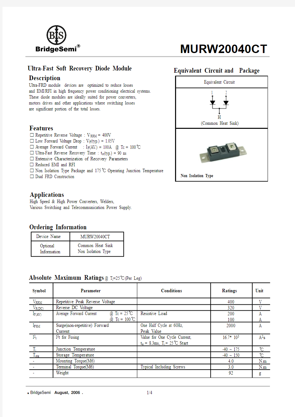
Non Isolation Type
Device Name MURW20040CT Common Heat Sink Non Isolation Type
Optional Information
Ordering Information
Equivalent Circuit and Package
Thermal Characteristics
Symbol
Parameter
Values
Unit Conditions R th(j-c)
Thermal Resistance(Non Isolation Type)
Min.
Typ.
Max.-
Junction to Case
0.31
℃/W
-
Electrical Characteristics @ T j =25℃(unless otherwise specified)
Symbol
Parameter Values
Unit
Conditions
V R V FM I RRM T rr
Cathode Anode Breakdown Voltage
Maximum Forward Voltage Repetitive Peak Reverse Current
Reverse Recovery Time
I R = 100uA
I FM = 100A, T c = 25℃I FM = 100A, T c =100℃T C = 100℃, V RRM applied I FM = 100A, V R = 200V di/dt=-100A/us
Min.
Typ.Max.-1.31.11.0120-V V V mA ns ns
400-----
-1.000.93-90120
T c = 25℃T c = 100℃
Performance Curves
Fig. 1 : Typical Forward Voltage Drop
vs. Instantaneous Forward Current Fig. 2 : Typical Reverse Recovery Time vs. -di/dt
Fig. 3 : Transient Thermal Impedance(Z thjc) Characteristics
Fig. 4 : Forward Current Derating Curve
Package Out Line Information
Dimensions in mm
Package : W10 Series